
Book Appointment Now

GC INDUS / MANUFACTURING KNOWLEDGE
5 Tolerance Stack-Up Mistakes That Ruin Part Assemblies

Understanding what is tolerance stack-up is essential. Tolerance stack-up is the cumulative effect that individual part tolerances have on the final fit and function of an assembly when those parts are combined. Because no part is machined to an exact dimension, small variations add up across a chain of mating features, and if not analyzed correctly, that accumulated variation can cause interference, excessive play, or misalignment. Most assembly failures trace back to a handful of avoidable mistakes in how this analysis is done, not to the tolerances themselves.
1. Ignoring What Tolerance Stack-Up Means for Assembly Fit
Tolerance stack-up is the cumulative variation that builds up across a chain of mating dimensions in an assembly, not the tolerance on any single part. The mistake begins when teams treat it as a single-part concern instead of a design discipline that spans the whole chain. This is particularly relevant for what is tolerance stack-up.
What is meant by tolerance stack-up in the context of assembly design?
Tolerance stack-up calculations represent the cumulative effect of individual part tolerances against an assembly requirement, asking whether the parts that make up an assembly will actually go together and function. Every part in a chain carries its own allowable variation. When those parts mate, a shaft into a bearing bore, a bracket stacked on a housing, each tolerance range adds a layer of uncertainty, and that uncertainty compounds across every part in the chain. Multi-part assemblies with tight-fit requirements are the most exposed: bearing seats, sealed housings, and stacked bracket assemblies fail in ways single-dimension parts never will, because the error path runs through several interfaces before it reaches the feature that matters.
Why is tolerance stack-up analysis critical for on-time delivery and cost control?
Skipping stack-up analysis at the design stage, instead of catching it after parts are already machined, is the first and costliest mistake in this list. Every other mistake in this article is a variation on the same root problem: analysis performed too late, or not at all. At GC INDUS, stack-up review happens before a quote is finalized, because catching an incompatible tolerance chain on a drawing costs a review meeting; catching it after 500 housings are cast costs a redesign, a scrap bin, and a missed delivery date.
2. Treating Worst-Case and RSS Methods as Interchangeable
Worst-case and RSS analysis produce different tolerance budgets for the same assembly, and picking the wrong one either overspends on precision or under-protects against failure.
When should you use worst-case vs. RSS methods in your manufacturing process?
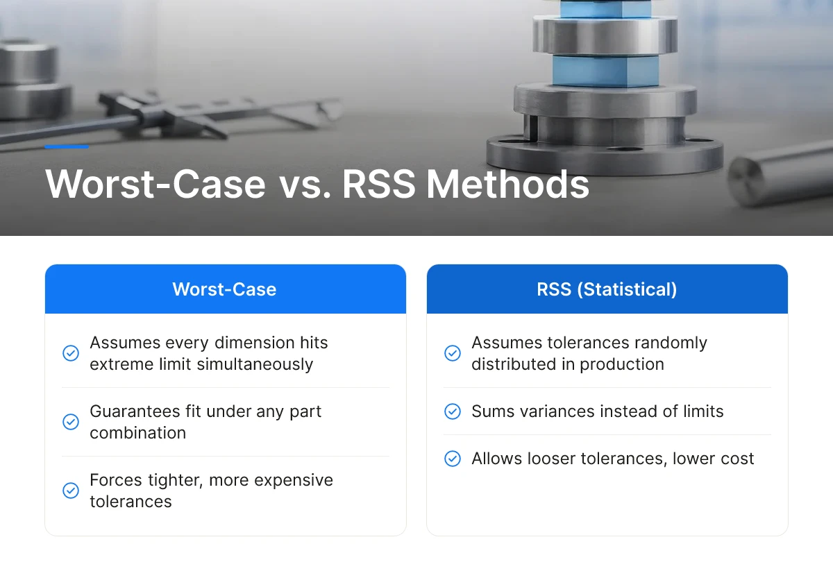
Worst-case analysis assumes every dimension in the chain hits its extreme tolerance limit at the same time, which guarantees fit under any combination of parts but forces tighter, more expensive tolerances on every contributing feature. RSS (root-sum-square), a statistical method, assumes tolerances are randomly distributed across a production run and sums their variances instead of their extremes, it allows looser individual tolerances but accepts a small statistical risk that some assemblies will fail to fit. Worst-case fits low-volume, safety-critical stacks where a single failure is unacceptable, a medical implant housing or an aerospace fastener chain. RSS suits high-volume production runs where process control data confirms the variation actually behaves the way the statistics assume.
How do worst-case and RSS methods affect your tolerance specifications?
The common mistake is applying RSS math without first verifying the process is in statistical control. RSS’s looser tolerance allowance depends on parts actually clustering near nominal, not drifting or shifting mid-run; without process capability data behind it, the “acceptable risk” the formula promises is an assumption, not a fact. When considering what is tolerance stack-up, this point stands out.
3. Skipping the Step-by-Step Calculation and Guessing Instead
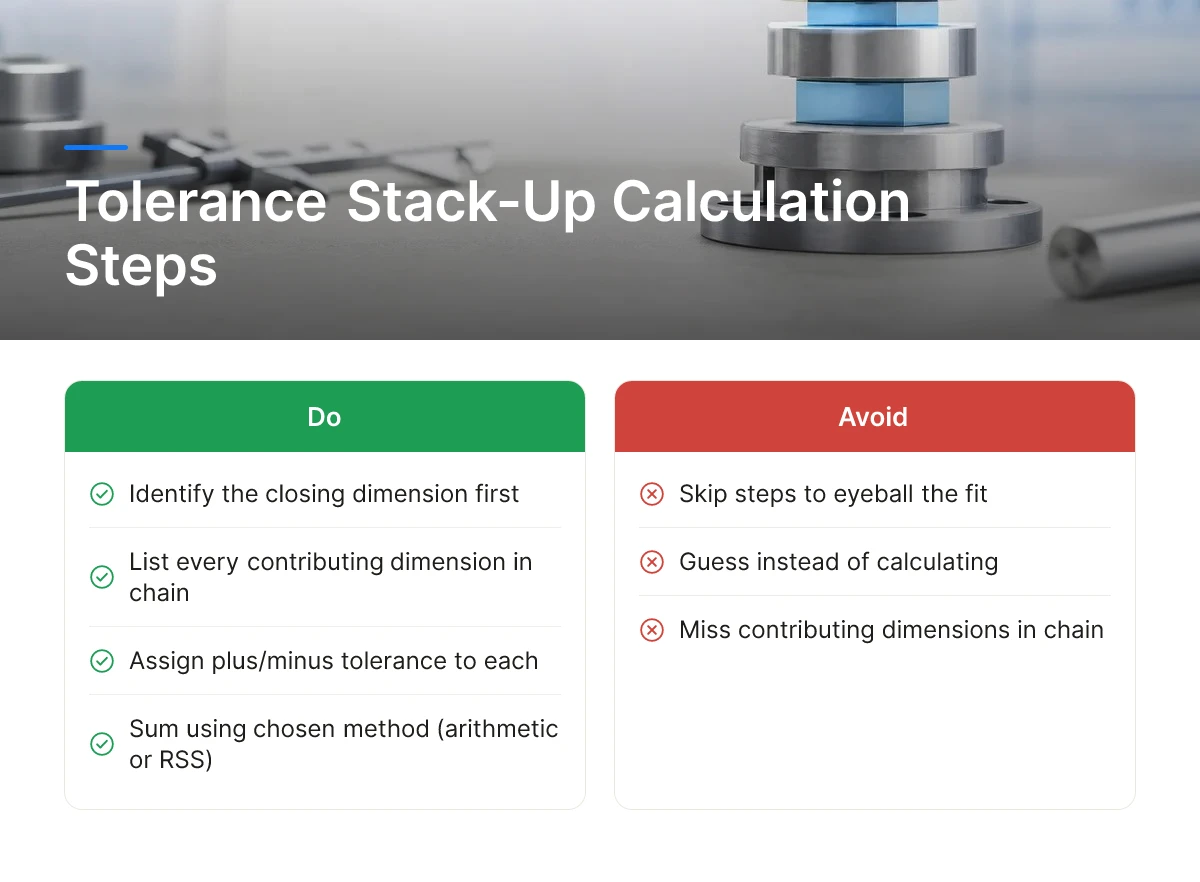
A tolerance stack-up calculation follows a fixed sequence, closing dimension, contributing chain, signed tolerances, sum, and skipping steps to “eyeball” a fit is how assemblies fail quality inspection.
What are the formulas and actual numbers used in tolerance stack-up calculations?
The sequence starts by identifying the closing dimension, the gap or fit you’re trying to guarantee, then listing every contributing dimension in the chain between the fixed datum and that feature, assigning a plus/minus tolerance to each, and summing per the chosen method: arithmetic addition for worst-case, or square-root-of-sum-of-squares for RSS.
Can you walk through a complete calculation example with real manufacturing dimensions?
Take a three-part stack: a housing at 50.00mm ±0.05mm, a spacer at 20.00mm ±0.03mm, and a shaft collar at 10.00mm ±0.02mm, closing on a target gap. Worst-case sums the tolerances directly: ±0.10mm total. RSS takes the square root of the sum of squares of each tolerance (0.05² + 0.03² + 0.02²), yielding roughly ±0.062mm, a tighter, more realistic budget if the process is genuinely in statistical control.
The common shortcut mistake is rounding intermediate tolerance values before the final sum, rounding 0.062 to 0.06, then rounding again downstream, which silently inflates or hides the real risk. Documenting the full calculation, not just the final number, matters because a design review or an audit needs to trace how the answer was reached, not just what it was.
4. Building an Incomplete or Incorrect Tolerance Vector Loop
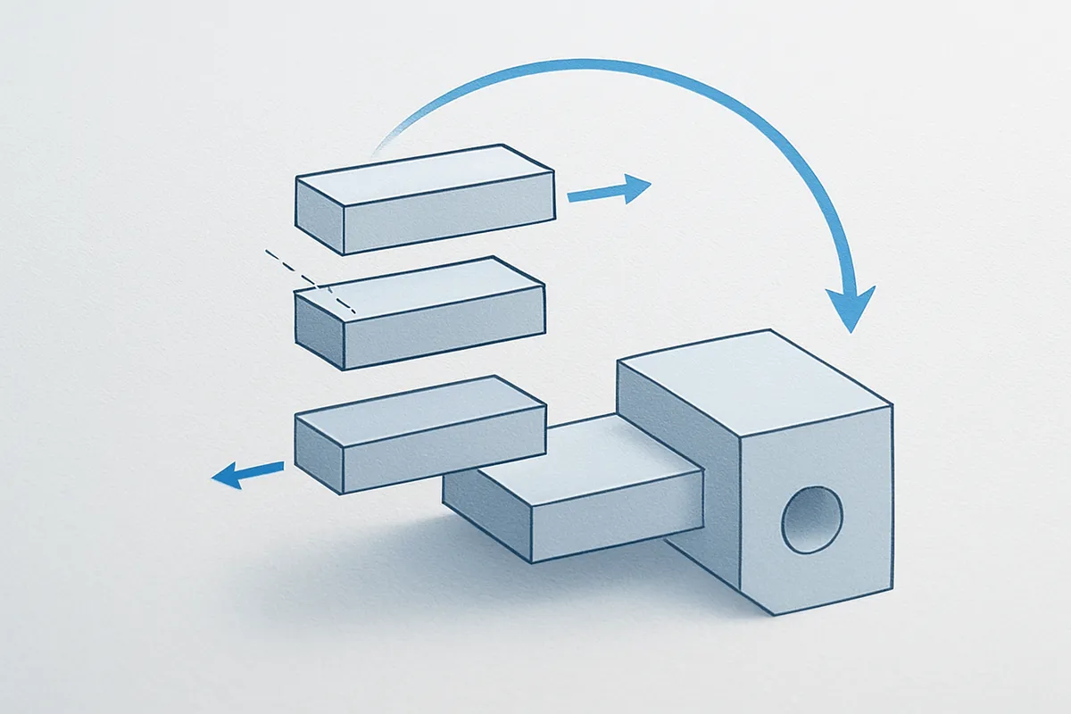
A tolerance vector loop is a closed diagram tracing every dimension from a fixed datum to the feature being analyzed and back, and missing one link understates real variation. For those exploring what is tolerance stack-up, this matters.
How do you construct and use a tolerance vector loop to identify critical dimensions?
The loop concept treats each dimension as a vector with a direction and magnitude, chained together until the loop closes back on itself. Any dimension left out of the loop, or any vector assigned the wrong direction, silently understates the actual variation the assembly will see, the math still produces a number, but it’s the wrong one. Construct one by starting at a fixed reference surface, following each mating interface in sequence, and closing the loop precisely at the dimension you’re solving for.
The common mistake is choosing a loop path that skips a floating datum or an assembly-induced shift, fastener clearance, a slip fit, a gasket compression, that adds real variation but doesn’t appear on the nominal drawing. This is where understanding what is tolerance stack-up as a geometric, not just arithmetic, problem separates a correct analysis from an incomplete one.
5. Analyzing Stack-Up Without Integrating GD&T Controls
Running stack-up math on plus/minus linear dimensions alone while ignoring geometric controls misses variation that position, flatness, and perpendicularity actually govern.
Which GD&T symbols and controls should be included in your stack-up analysis?
GD&T symbols, true position, perpendicularity, flatness, define real-world variation on a part in ways coordinate dimensions alone can’t capture, because they control orientation and form, not just size. Datum precedence order changes which surfaces actually control the stack-up path: the primary datum constrains the part first, and a stack-up built on the wrong precedence traces variation through a surface that isn’t actually load-bearing in the real assembly.
The common mistake is mixing coordinate-style tolerances with GD&T features without converting them to a common basis before summing them, the two systems measure variation differently, and combining them without translation produces a number that looks precise but isn’t. The fix: bonus tolerance from material condition modifiers like MMC or LMC can be included in the budget, but only when explicitly analyzed feature by feature, never assumed as a blanket allowance. GC INDUS’s inspection protocols, backed by ISO 9001 and ISO 13485 quality systems, verify GD&T callouts against the stack-up model before parts ship, the step where an incomplete analysis usually gets caught.
6. Overlooking the Real-World Consequences of a Bad Stack-Up
A bad stack-up shows up on the shop floor as parts that won’t assemble, wear out early, or misalign in ways that break function, not as an abstract math error. This directly impacts what is tolerance stack-up outcomes.
What assembly failure case studies illustrate the cost of inadequate stack-up analysis?
Interference fits are the most visible failure: a shaft that should slide into a bore instead requires a press or a mallet, damaging both parts and hiding the underlying tolerance error. On the other end, excessive play from too much accumulated clearance causes premature wear in bearings, hinges, and sliding mechanisms, the assembly works on day one but fails months later in the field. Misalignment is subtler still, showing up as optical components out of focus, connectors that mate at an angle, or seals that leak under vibration.
The cost mechanism is timing. A dimension caught during design review costs a drawing change. The same error caught after 5,000 units are molded or machined costs scrapped material, re-tooling, and a re-cut schedule.
Downstream, this triggers assembly-line stoppages: a batch fails fit-check, inspection puts the line on hold, and engineering scrambles for root cause while inventory backs up. In precision manufacturing, where tight tolerances and multi-part chains are the norm, small individual errors compound fast, this is exactly why understanding what is tolerance stack-up matters before parts reach the line, not after.
7. Relying on Manual Excel Spreadsheets Without Structure
Ad hoc Excel sheets fail at stack-up analysis when they lack a fixed structure, a consistent way to enter, sum, and trace every contributing dimension.
What Excel templates or formulas can help automate your stack-up calculations?
A workable structured sheet needs a dedicated row or column for each contributor in the chain, a plus/minus tolerance value tied to that dimension, a method flag marking whether it’s worst-case or root-sum-square (RSS), and a running sum formula that updates automatically as inputs change.
The common failure mode is hard-coding the final tolerance number instead of linking it back to the source part dimensions. When a supplier tightens or loosens a tolerance on one component, a hard-coded sheet doesn’t update, the analysis silently goes stale, and nobody notices until the assembly fails fit-check. This is particularly relevant for what is tolerance stack-up.
A basic template can flag this before it becomes a production problem: a conditional check that highlights when the cumulative sum exceeds the design target, forcing a review before the drawing is released.
Even a well-built spreadsheet has a ceiling. Manual sheets handle simple linear chains fine, but they don’t scale to loops with a dozen-plus contributors or true 3D vector paths, that complexity is where dedicated tolerance analysis software takes over.
8. Choosing Analysis Methods Without Matching Tools to Complexity
Pick a tool that matches your assembly’s complexity, not your budget, a mismatch in either direction creates its own risk.
How does tolerance analysis software improve upon manual stack-up methods?
Manual spreadsheets work for simple 1D chains with a handful of contributors. Mid-range 1D/2D stack-up calculators add structure and repeatability for moderately complex assemblies. Enterprise-grade 3D tolerance simulation software automates vector loop construction across an entire assembly and runs Monte Carlo simulation across thousands of virtual builds, cutting the chance that a contributor gets left out of the chain entirely.
What features should you look for when selecting a tolerance stack-up tool?
Look for GD&T-aware input that reads geometric tolerances directly rather than forcing a translation to plus/minus values, sensitivity analysis that flags which dimension drives the most variation in the final result, and revision tracking that keeps the model current when a drawing changes. When considering what is tolerance stack-up, this point stands out.
The mistake runs in both directions. Some teams adopt full 3D simulation software for a simple two-part linear stack, adding cost and setup time with no real benefit, over-tooling. Others stay on manual spreadsheets for complex multi-axis assemblies with dozens of contributors, missing interactions that only a proper vector loop model catches, under-tooling.
How to Choose the Right Tolerance Stack-Up Approach for Your Assembly
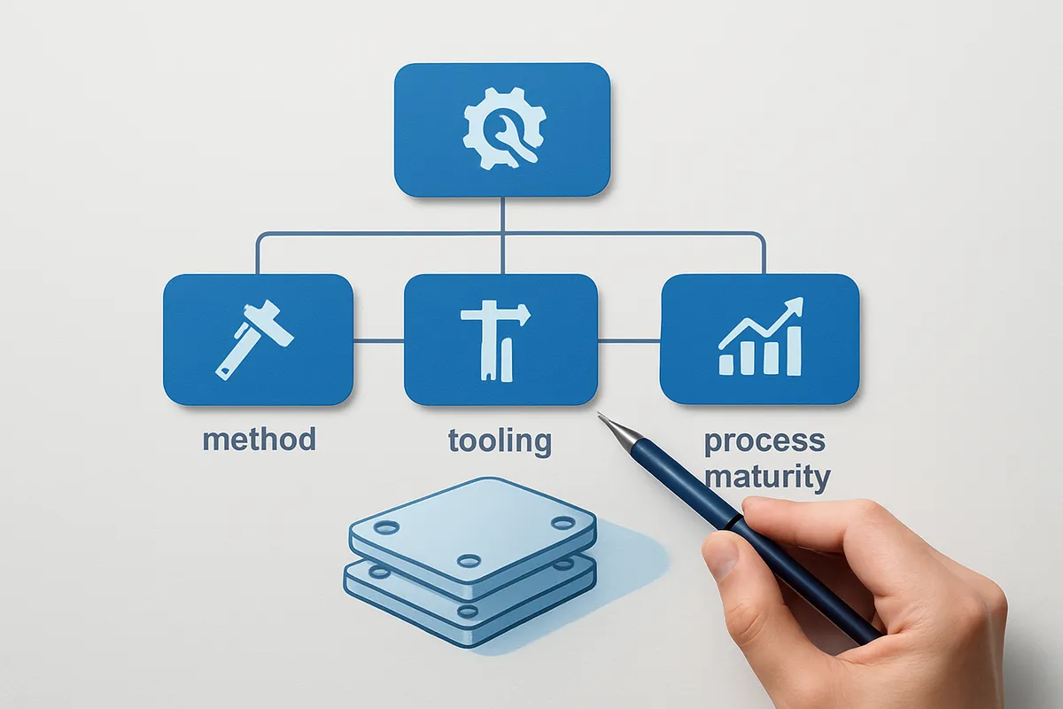
Match the method to three factors: how many dimensions feed the chain, how many units you’re building, and how critical the fit is to safety or function.
For a simple, low-volume assembly with a critical fit, a sealing surface, a safety interlock, a precision alignment, worst-case analysis on a structured spreadsheet is the right call. It’s conservative by design and easy to audit line by line. For complex, high-volume production with many contributors, RSS analysis paired with dedicated tolerance simulation software fits better, because it reflects real statistical variation across thousands of parts instead of a pessimistic worst case.
Before leaning on any statistical method, verify actual process capability data from the machines and suppliers producing the parts, RSS assumes a distribution, and that assumption only holds if the process backs it up. Re-run the stack-up whenever a supplier changes or a tolerance on a drawing is revised; a stack-up validated once and never revisited is a stack-up quietly going stale.
This is also where the manufacturing partner matters. GC INDUS documents GD&T requirements and inspection protocols at the quoting stage, not after parts are cut, so tolerance decisions get made with real process capability data behind them, holding tolerances as tight as ±0.001mm across CNC, casting, and molding under ISO 9001 and ISO 13485 quality systems. For those exploring what is tolerance stack-up, this matters.
Frequently Asked Questions
How does each part’s tolerance contribute to the final assembly fit and function?
Each part’s allowed variation adds to (or subtracts from) the total gap or interference in the finished assembly, so no single tolerance can be judged in isolation. Tolerance stack-up calculations model this cumulative effect against a specific assembly requirement, such as a hole aligning with a fastener or a latch engaging cleanly. Loose tolerances on individual components can combine into a fit failure even when every part passes its own inspection.
What happens when tolerances stack up in the worst possible direction?
Every dimension hits its maximum or minimum limit at once, pushing the assembly to its worst-case gap or interference condition. This scenario, called worst-case stack-up, assumes no compensating variation between parts. It’s rare in practice, but ignoring it during design leaves no margin for the times when it does happen on the production line.
What are the consequences of improper tolerance stack-up analysis on a production line?
Poor stack-up analysis causes parts that won’t assemble, mechanisms that bind, and products that fail final inspection after production has already started. Fixes at that stage mean scrapped inventory, line stoppages, and rework costs far higher than catching the error at the design stage. Repeated failures also point to systemic gaps in datum structure or GD&T practice that keep resurfacing across product lines.
How can precision manufacturers avoid the pitfalls that lead to assembly failures?
Manufacturers avoid failures by combining statistical or worst-case stack-up analysis with a disciplined datum structure and full inspection protocols before parts reach the assembly line. Accounting for thermal expansion, assembly sequence, and part deflection matters as much as the nominal dimensions themselves. GC INDUS applies this discipline through ISO 9001 and ISO 13485 quality systems, holding tolerances to ±0.001mm across CNC, casting, and molding so cumulative variation stays inside the design margin.
Conclusion
Tolerance stack-up decides whether precision parts actually fit together, not just whether each one passes inspection on its own. The takeaways: run worst-case or statistical stack-up analysis before finalizing a design, build a clear datum structure instead of tolerancing features ad hoc, and account for real-world factors like thermal expansion and assembly sequence that specs on paper tend to ignore. Skipping this step is what turns individually “good” parts into a failed assembly. Before your next production run, pull the tolerance chain for your tightest-fit assembly and check it against actual process capability data, not catalog defaults.
Recommended Articles
Explore more from our content library:


