
Book Appointment Now

GC INDUS / MANUFACTURING KNOWLEDGE
7 Design Rules for Better Investment Casting Parts

Better investment casting parts come from designing for the process, not around it: uniform wall thickness, generous fillets, controlled draft, and tolerances set to match what the lost-wax method and alloy shrinkage can actually hold. Getting these seven rules right at the design stage—not during quality inspection—cuts scrap, avoids costly rework, and shortens the path from prototype to production part.

1. Design Investment Casting Parts Around Uniform Wall Thickness
Uniform wall thickness is the single biggest factor separating defect-free investment casting parts from parts riddled with shrinkage porosity and surface sinks.
The mechanism is thermal: thick sections stay molten longer than adjacent thin sections, and as the thick region finally solidifies, it pulls metal from itself because the feed path has already frozen shut. That creates internal voids you cannot see until X-ray or sectioning catches them. Rather than chasing a fixed ratio, treat thickness change as something that should happen gradually across a section, never as an abrupt step from thick to thin, abrupt jumps are what concentrate the shrinkage risk.
This rule matters most for complex geometry where metal has to flow predictably through multiple branches, impellers, mounting brackets, and valve bodies are typical examples where uneven sections cause the most scrapped parts.
The differentiator teams miss: wall thickness targets are not universal. Shrinkage behavior varies by alloy family, so a wall thickness rule tuned for a nickel alloy will not necessarily hold for an aluminum or stainless casting. Lock the alloy before finalizing section thickness, not after.
2. Add Fillets and Radii Instead of Sharp Internal Corners
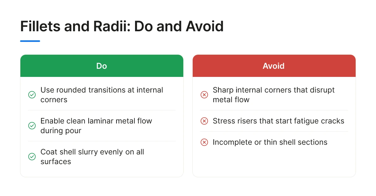
Rounded transitions instead of sharp internal corners cut stress concentration and let molten metal and ceramic shell fill cleanly during the pour.
Sharp corners disrupt laminar metal flow, creating turbulence at the exact point where the part needs the cleanest fill. Under load, that same corner becomes a stress riser, a starting point for fatigue cracks long after the part is in service. The ceramic shell has its own version of this problem: sharp internal angles are physically harder for shell slurry to coat evenly, raising the odds of an incomplete or thin shell section right where strength matters most.
Fillets matter most on structural and load-bearing components, where fatigue life over years of service, not just a single load test, determines whether the part survives.
The differentiator: this defect shows up disproportionately in one specific workflow, engineering teams that port a CAD model originally drawn for CNC machining straight into a casting tool without adding radii. A machined part tolerates a sharp internal corner; a cast one rarely does.
3. Set Draft Angles Even Though Investment Casting Uses No Metal Die
Draft angles still matter in investment casting because the wax pattern, not the final part, has to release cleanly from reusable injection tooling.
Here is the mechanism: wax is injected into a metal die to form the pattern, and without draft, that wax pattern distorts or tears as it’s pulled from the tool cavity. The final ceramic shell is broken away rather than opened, so people assume draft is irrelevant to investment casting parts, it isn’t, it just applies one step earlier than in die casting. In die casting, draft affects the metal part directly because the die closes around solidified metal; in investment casting, draft only governs the wax stage.
This rule applies to parts built for production volumes using hard aluminum or steel wax-injection tooling, where the same tool cycles thousands of times.
The nuance competitors skip: low-volume runs or prototypes made from 3D-printed wax or sacrificial patterns don’t go through a reusable die, so draft requirements can often be relaxed or dropped entirely for that stage of a project.
4. Specify Tolerances That Match Alloy Shrinkage, Not Just Drawing Ideals
Achievable tolerances on investment casting parts come from mold design and alloy shrinkage math, not from copying a machined-part drawing’s tolerance block.
What role does the lost-wax process play in achieving dimensional accuracy?
The lost-wax process produces tighter as-cast accuracy than sand or shell molding because the wax pattern and ceramic shell replicate fine detail without a parting line disturbing the surface. Investment casting typically holds around ±0.005 inches per inch of linear dimension as a general benchmark, though actual results depend on geometry and alloy.
How do mold design and material shrinkage affect final part tolerances?
Every alloy shrinks by a different amount as it cools from pour temperature to room temperature, so foundries build shrinkage allowance directly into the mold and tooling dimensions. Get that allowance wrong for the specified alloy and every part comes out consistently oversized or undersized, not randomly out of spec.
Distinguish as-cast tolerances, which apply across a whole surface, from mating features and interfaces that need post-cast machining to hit a precision spec. Parts with critical bore diameters or flatness call-outs are the best fit for this hybrid approach.
The differentiator: it’s often cheaper to loosen the casting tolerance across the whole part and finish-machine the one or two features that truly need precision, rather than paying a shell and mold premium to hold a tight tolerance everywhere.

5. Choose Alloys Based on Service Conditions, Not Just Availability
Alloy selection for investment casting parts should follow the part’s mechanical and environmental demands, not whichever material is easiest to source.
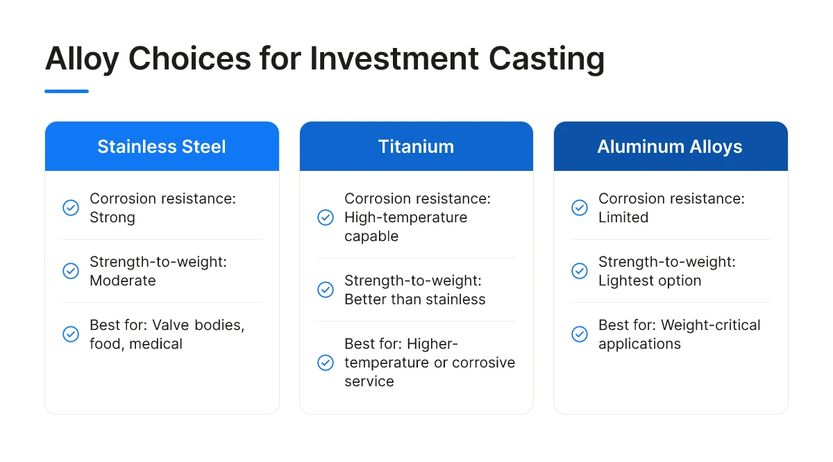
How do titanium, stainless steel, and aluminum alloys differ in investment casting performance?
Stainless steel offers strong corrosion resistance and moderate strength-to-weight ratio, making it a common default for valve bodies and food or medical components. Titanium delivers a better strength-to-weight ratio and holds up in higher-temperature or corrosive service, but it costs more and is harder to cast cleanly. Aluminum alloys are the lightest option and cast with high fluidity, but they trade off top-end strength and heat tolerance against stainless and titanium.
Each alloy also has its own fluidity and shrinkage rate, and those two properties determine how tightly you need to apply the wall-thickness, fillet, and tolerance rules covered above, a highly fluid alloy tolerates thinner walls, while a sluggish one needs more generous transitions to avoid misruns.
This approach suits engineers juggling weight, temperature exposure, and mechanical load requirements within a single part, where no one alloy is an obvious default.
The differentiator: lock the alloy decision before finalizing wall thickness or tolerance specs, not after, changing alloy late forces a rework of both because shrinkage and fluidity shift the numbers you already signed off on.
6. Design Features to Reduce Porosity and Shrinkage Defects at the Source
Most porosity, shrinkage cavities, and surface inclusions in investment casting parts trace back to wall thickness transitions and gating decisions made before the mold is ever built.
What are the most common casting defects, and what causes them?
Porosity forms when trapped gas or shrinking metal cannot escape during solidification, usually at thick sections isolated from feed paths. Shrinkage cavities appear where a heavy section solidifies last and pulls metal from itself because no riser can reach it. Surface inclusions come from turbulent metal flow picking up mold material or oxide film, often a symptom of poor gating angles rather than a foundry error.
Riser and gating placement are not decided in isolation, they follow the part’s own geometry. A designer who tapers wall thickness gradually and directs mass toward a single heavy section gives the foundry a natural path to place risers where they will actually feed the last metal to solidify. Uneven walls force compromises that no amount of process tuning can fully fix.
Design and process controls work together, not in sequence. Alloy selection affects shrinkage rate, and mold preheat temperature affects fill behavior, but both only perform as expected when wall geometry supports directional solidification.
This matters most for parts moving from prototype to production, where a defect rate acceptable in a five-piece prototype run becomes a costly rework line at 5,000 units.
7. Plan Inspection and Quality Verification Into the Design, Not After It
Design accessible datums and inspection surfaces before tooling starts, so CMM, X-ray, or dye penetrant checks do not require redesign later.
How do we verify compliance with aerospace, medical, or automotive quality standards?
Each inspection method imposes its own design demand. Coordinate measuring machines need clear, repeatable datum surfaces free of parting lines or flash. X-ray inspection for internal porosity needs sufficient wall access and thickness uniformity to read consistently. Dye penetrant testing for surface cracks needs a finish clean enough to avoid false positives, which ties back to how the pattern and shell were built.
Compliance needs should be confirmed at the design stage, not after drawings are released. Aerospace and automotive programs typically require dimensional reports tied to specific tolerance classes, while medical device parts require material traceability and documented inspection protocols under ISO 13485. Raising these requirements during design review avoids late-stage geometry changes that ripple through tooling.
This step matters most in regulated industries, where a non-conformance found after production start halts a batch rather than a single part.
Most design guides treat inspection as a post-production checklist. Deciding datum placement during design instead shortens first-article inspection, since the fixture and measurement plan are ready before the first shell is poured.
How to Choose the Right Design Approach for Your Investment Casting Parts
Base the design approach on three variables: production volume, how critical the tolerance is, and how complex the geometry needs to be.
When is investment casting more cost-effective than die casting or sand casting?
Investment casting carries a moderate tooling investment compared to die casting’s higher upfront tooling cost, but it produces tighter as-cast tolerances and finer detail without secondary machining. For low-to-mid volume runs with complex internal geometry, that tradeoff favors investment casting. Die casting pulls ahead once volume climbs high enough to spread its heavier tooling cost across many units. CNC machining from billet suits very low volumes or single prototypes where no tooling cost is acceptable at all, though material waste and cycle time run higher per part.
Lead time, minimum order quantity, and scalability shift this calculation as volume grows. A supplier that only accepts large minimum order quantities forces overstock on a design still being validated. GC INDUS accepts orders from 1 piece, which lets a design move from prototype to low-volume production without switching vendors or re-qualifying a new supplier.
What capabilities and certifications should we verify in a casting partner?
Check for ISO 9001 quality management as a baseline, and ISO 13485 specifically if the part serves a medical application. Confirm the partner’s in-house finishing, heat treatment, surface treatment, assembly, since outsourcing these steps adds handoffs and lead time. GC INDUS holds both certifications and machines to tolerances as tight as ±0.001mm, covering the tighter end of what casting-plus-machining programs demand.
Bring a casting partner into the design review before drawings are finalized. Catching a wall thickness or draft angle issue at that stage costs a revision; catching it after tooling is cut costs a rebuild.

Frequently Asked Questions
How do wall thickness, draft angles, and feature complexity impact castability?
Uneven wall thickness, missing draft, and overly complex features are the most common causes of casting defects and rework. Wall thickness variation drives uneven cooling, which causes shrinkage porosity and warping. Draft angles help pattern removal and reduce ceramic shell damage during dewaxing. Sharp internal corners concentrate stress and disrupt metal flow, so smart transitions and fillets matter as much as the wall dimension itself.
What are the trade-offs between investment casting lead time and precision versus CNC machining?
Investment casting needs tooling and multi-step processing, so lead times run longer than CNC machining but deliver complex net-shape geometry in one process. CNC machining cuts single parts faster with no tooling wait, but struggles with intricate internal passages or organic shapes casting handles natively. Typical investment casting tolerances run around ±0.005 inches per inch of dimension, often followed by machining on critical features to tighten specific tolerances further.
How does production volume impact unit cost and delivery schedules for investment casting?
Higher volumes spread tooling cost across more parts, lowering unit price and stabilizing delivery schedules once patterns are qualified. Low-volume or prototype runs carry a higher per-piece cost because tooling and setup dominate the budget. GC INDUS accepts orders from 1 piece, letting engineering teams validate a casting design before committing to full production tooling.
Which applications require the precision and complexity that investment casting uniquely provides?
Aerospace, medical device, and automotive components with complex internal geometry, thin walls, or tight dimensional control rely on investment casting because it produces near-net-shape parts that other processes can’t replicate economically. Medical implants and surgical instruments benefit from the fine surface finish and material integrity investment casting delivers. Turbine blades, valve bodies, and housings with internal channels are classic examples where machining alone would be cost-prohibitive or geometrically impossible.
How do we evaluate a manufacturer’s ability to meet our tolerance, quality, and delivery requirements?
Check certifications, request tolerance capability data, and review inspection protocols before committing to a supplier. ISO 9001 confirms a documented quality system, while ISO 13485 signals medical device compliance for regulated parts. GC INDUS holds both certifications, backs claims with full inspection protocols, and supports tolerances as tight as ±0.001mm on finished components after machining.
Conclusion
Manufacturable investment casting parts start with wall thickness discipline, adequate draft, and tolerance targets set before the CAD file goes to quote. Skipping DFM review at the design stage is the single biggest driver of rework, missed deadlines, and cost overruns downstream. Treat casting and machining as complementary, not competing, processes—cast the complex geometry, then machine the critical features that need tighter control.
Before your next RFQ, send your 3D model to a manufacturing partner for a DFM review rather than a quote alone. GC INDUS reviews wall thickness, draft, and tolerance callouts against ±0.001mm machining capability and ISO 13485 quality protocols before production starts, with MOQs from 1 piece for validation runs.
Recommended Articles
Explore more from our content library:


