
Book Appointment Now

GC INDUS / MANUFACTURING KNOWLEDGE
A Complete Guide to Burr Removal in Precision Machining

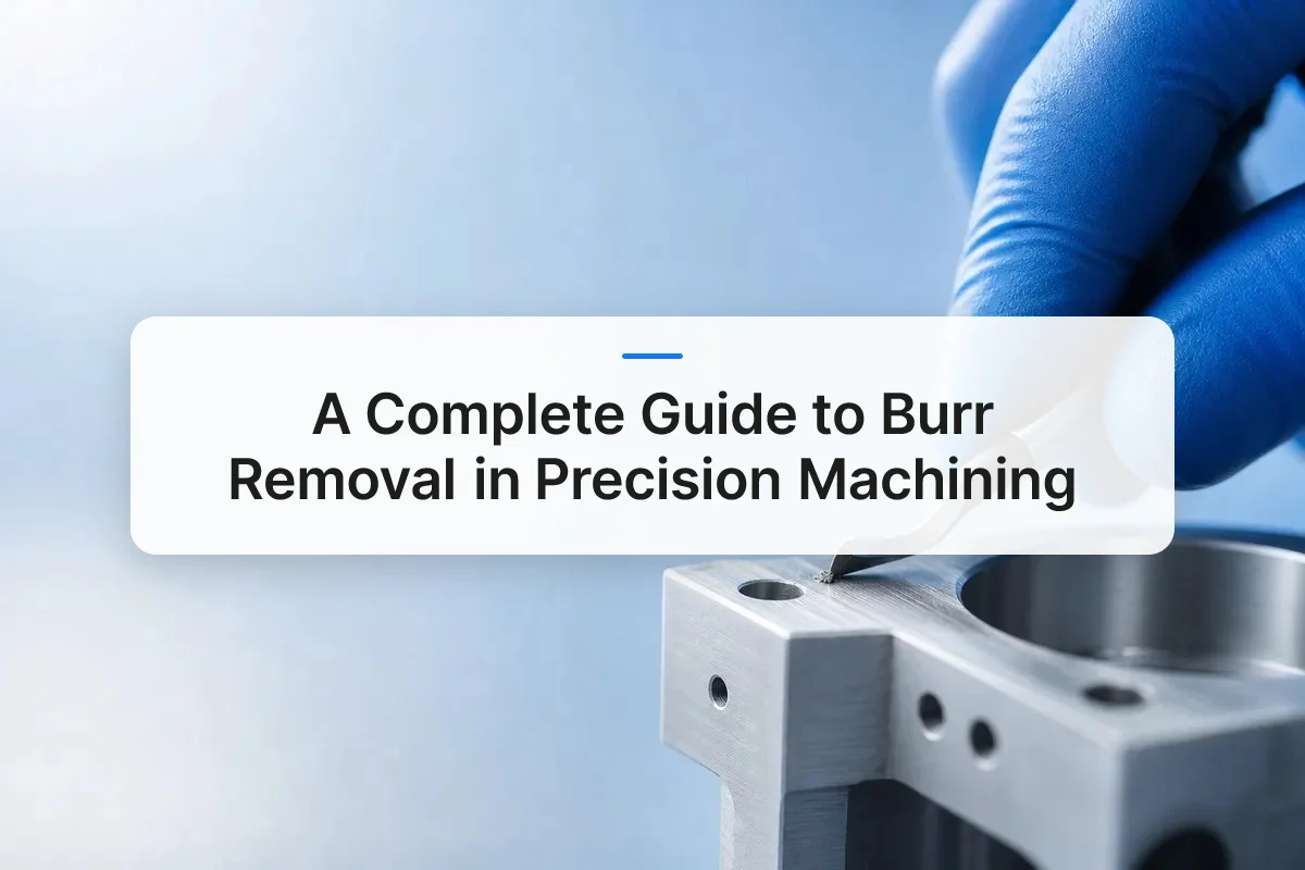
Burr removal precision machining is the process of eliminating small, unwanted projections of material—called burrs—that form on a workpiece during cutting, milling, drilling, or turning. Left in place, burrs compromise dimensional accuracy, create assembly failures, and introduce safety hazards. Effective deburring restores part geometry to specification and is a non-negotiable step in aerospace, medical, and automotive production where surface finish and compliance standards are strictly enforced.
What Burr Removal Precision Machining Actually Means
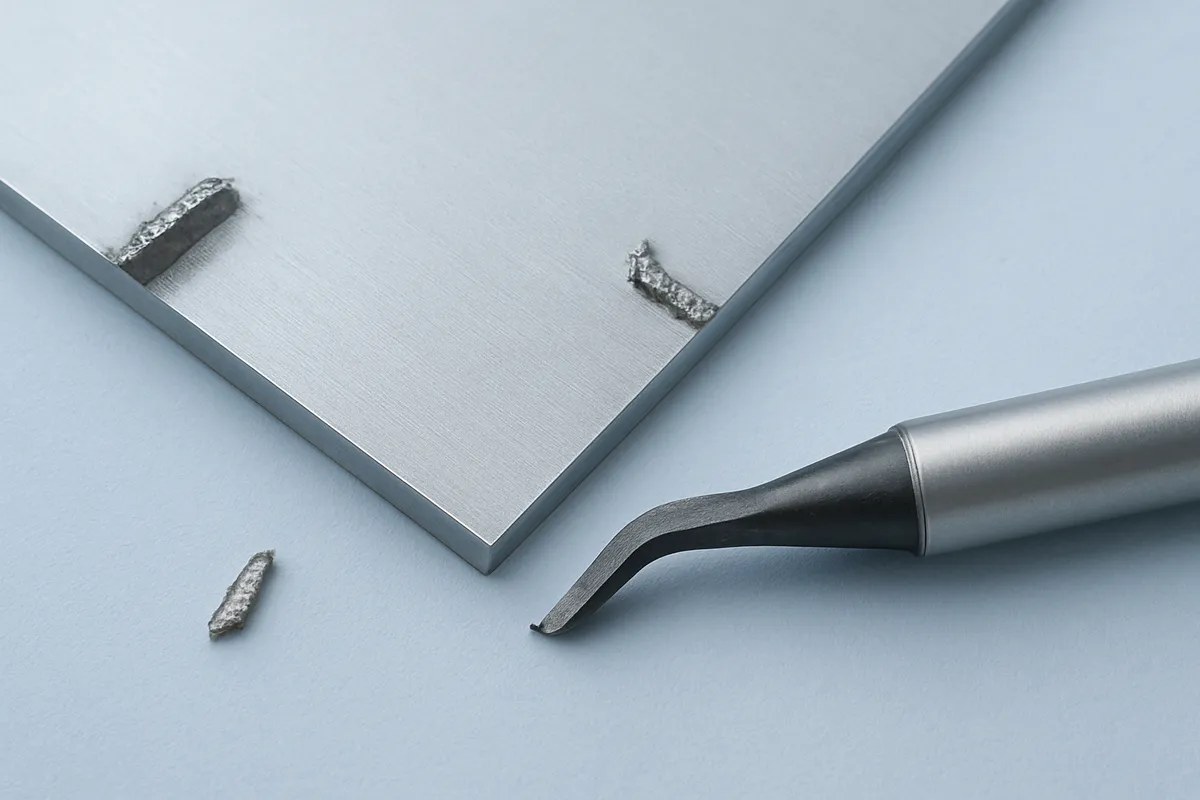
A burr is a raised projection of displaced material that stays attached to a workpiece after a cutting or shearing operation—distinct from surface roughness or tool marks. Understanding burr removal precision machining begins with recognizing that burrs are not a cosmetic nuisance but a dimensional defect with real functional consequences.
Unlike surface roughness, which describes the microscopic texture of a machined face, a burr is a physical protrusion: material that failed to separate cleanly and instead folded over the workpiece edge. It occupies real space, alters part geometry, and cannot be corrected by tolerance stacking or measurement averaging.
Why Burrs Are a Functional Problem, Not Just a Cosmetic One
Burrs form through plastic deformation. As a cutting tool exits a workpiece, the material at the edge lacks the support needed to shear cleanly. Instead of separating, it bends and folds, leaving a thin fin or raised lip bonded to the part.
That deformation has direct functional consequences. In mating assemblies, a burr on one face prevents flush contact with the mating surface, creating dimensional mismatch that no amount of fastener torque corrects. At stress concentration points—holes, slots, and step features—burrs act as crack initiation sites under cyclic loading, accelerating fatigue failure. During manual handling, undeflected burrs on aluminum or steel edges cause lacerations.
Burr removal in precision machining is therefore a structural and safety requirement, not a finishing preference.
Regulatory and Surface Finish Standards That Apply to Deburring
ISO 13715 governs how edge condition—including burr presence and edge-break geometry—is indicated on technical drawings, giving manufacturers and inspectors a shared language for specifying and verifying deburring outcomes.
Each high-stakes sector adds its own layer. Medical device components produced under ISO 13485 require documented deburring steps with inspection records, because a retained burr in an implant or surgical instrument is a patient safety issue. Aerospace suppliers working to AS9100 standards treat edge condition as an inspected characteristic, not a shop-floor judgment call. Automotive Tier-1 suppliers face similar requirements under IATF 16949, where surface finish and edge-break specifications appear on control plans and are subject to process audits.
GC INDUS holds both ISO 9001 and ISO 13485 certifications, which means deburring and edge inspection are built into production workflows—not added as an afterthought before shipment.
Types of Machining Burrs and Where They Form
Four distinct burr geometries—Poisson, rollover, tear, and cut-off—each form through a different mechanism and appear at predictable locations on machined parts.
A Poisson burr forms when tool pressure pushes material sideways beyond the cutting edge rather than shearing it away. A rollover burr occurs when material folds over at the point where the tool exits the workpiece—the most common type seen on milled surfaces. A tear burr results from material being pulled and torn rather than cleanly sheared, typically leaving a ragged, irregular edge. A cut-off burr is the small stub of material left at the parting line in turning and parting operations.
How Burrs Form Differently in Milling Versus Drilling and Turning
Tool exit angle and feed direction determine which burr type dominates. In milling, rollover and Poisson burrs concentrate at exit edges where the cutter leaves the workpiece boundary. In drilling, the breakthrough moment creates tear burrs as the drill tip forces through the final layer of material before full penetration. Turning and parting operations produce cut-off burrs at the separation point.
Material ductility shapes burr character significantly. Aluminum and stainless steel deform rather than fracture, producing larger, more tenacious rollover burrs that resist simple wiping. Harder, more brittle materials tend to fracture at the edge, leaving smaller, more friable burrs that are easier to dislodge.
For burr removal precision machining, the highest-risk locations on any part are intersecting holes, thin-wall edges, and slot exits. These are the areas inspectors target first—and where undetected burrs most frequently cause assembly failures by preventing mating surfaces from seating correctly.
Material-Specific Burr Characteristics
The relationship between material properties and burr behavior is one of the most practical considerations in planning a deburring process. Ductile alloys such as aluminum 6061 and austenitic stainless steels like 316L tend to produce large, pliable rollover burrs that wrap around edges and resist removal by simple wiping or light abrasion. These materials require more aggressive mechanical action or electrochemical dissolution to achieve a clean, consistent edge break.
Titanium alloys present a particular challenge: they are both ductile enough to form tenacious burrs and reactive enough that thermal deburring methods must be applied with careful parameter control to avoid surface oxidation. Hardened tool steels, by contrast, produce smaller and more brittle burrs that fracture rather than fold—but those fragments can embed in adjacent surfaces or internal passages if not fully evacuated during the deburring cycle. Matching the deburring method to the specific material is therefore a core decision in any burr removal precision machining workflow.
Burr Removal Methods and Tools: A Practical Comparison
Burr removal precision machining splits across four core methods—manual, mechanical, thermal, and electrochemical—each suited to different geometries, materials, and batch sizes.
Manual Versus Automated Deburring: When Each Makes Sense
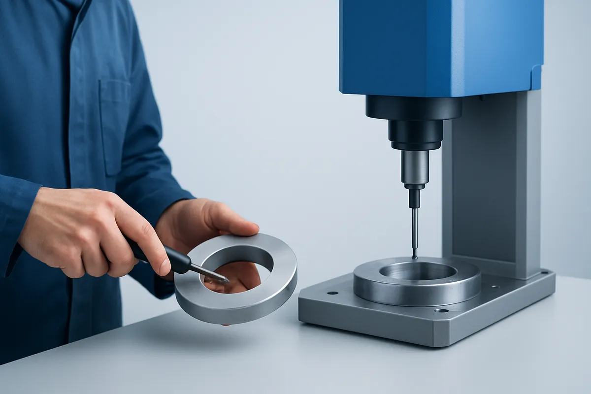
Manual deburring uses hand files, scrapers, and abrasive stones to give the operator direct tactile feedback on edge condition. That control makes it well suited to complex external geometries and low-volume prototype runs where tooling investment is hard to justify.
The consistency risk is structural, not incidental. As an operator fatigues across a shift, applied pressure and dwell time drift—producing edge radii that vary part to part even when the same person runs the same tool. For a tolerance-critical component, that variation can be as damaging as the original burr.
Mechanical methods—tumble finishing, vibratory bowls, brushing, and abrasive belt machines—eliminate that variability by processing many parts simultaneously under controlled conditions. Engineers tune media type (ceramic, plastic, steel shot), media-to-part ratio, and cycle time to match the target material and required edge radius. Softer aluminum parts run with milder plastic media; hardened steel takes ceramic or steel shot at longer cycle times. The result is repeatable edge conditions across high-volume batches.
Thermal energy deburring (TEM) fires a controlled combustion pulse inside a sealed chamber. The heat burns thin burrs away without contacting the base part surface. It excels on complex internal geometries—intersecting bores and blind passages that no line-of-sight tool can reach. Parameter control is critical: combustion pressure and gas mixture must be calibrated precisely to avoid surface oxidation on the parent material.
Electrochemical deburring (ECD) removes conductive burrs through anodic dissolution, directing current through a shaped cathode positioned at the target feature. Because no mechanical force is applied, it suits hardened steels and internal features in aerospace and hydraulic components where edge geometry is tightly specified and part distortion is unacceptable.
Equipment Selection Criteria for Deburring Machines
Choosing a deburring method comes down to five decision variables engineers should assess before specifying a process.
- Part geometry complexity: External features with open access suit mechanical or manual methods; intersecting internal bores require TEM or ECD.
- Material: Conductive metals are candidates for ECD; non-conductive materials are not. Soft alloys may deform under aggressive mechanical media.
- Required edge radius specification: A tight, documented edge-break callout demands a repeatable process—vibratory finishing or ECD—over manual hand-filing.
- Batch size: High-volume production justifies mechanical or thermal capital equipment; single-piece or prototype work typically does not.
- Internal passages: Any feature that excludes line-of-sight tooling immediately narrows the viable options to TEM or ECD.
At GC INDUS, finishing decisions are made at the process planning stage—not after a quality escape—so the deburring method is matched to part geometry and tolerance requirements before the first cut runs.
How to Prevent Burrs From Forming in Precision Machining
Controlling cutting parameters, tool geometry, toolpath exits, and edge callouts on drawings stops most burrs before they need removal.
How Cutting Parameters and Tool Selection Reduce Burr Formation
A sharp cutting edge with the correct rake angle shears material cleanly. A worn or incorrectly raked tool pushes material sideways instead of cutting through it, increasing plastic deformation at the workpiece edge, the direct cause of rollover burrs. Replacing or reconditioning tools before they degrade is one of the most reliable prevention levers available.
Feed rate, spindle speed, and depth of cut together determine chip load. An under-loaded tool rubs rather than cuts, generating heat and smearing material at exit edges. Chip-thinning during climb milling directs cutting forces away from the free edge, which measurably reduces rollover burr height at milled pockets and slots compared to conventional milling at the same exit point.
Toolpath programming adds another layer of control. Routing the tool to exit into a relief area, a pre-machined chamfer, or a lead-out arc keeps the cutting edge away from unsupported free edges, the geometry where classic rollover burrs form. This approach is standard practice for precision pocket and slot work where downstream burr removal precision machining would otherwise add cycle time and inspection steps.
Design intent matters too. Specifying chamfers or radii on drawing edges, per ISO 13715 edge condition callouts, tells the machinist that a clean break is required. That callout shifts edge quality from an afterthought into a planned process step, closing the loop between the designer’s intent and shop floor execution before the first chip is cut.
Manual Versus Automated Deburring: Costs, Timelines, and ROI
Manual deburring costs less to start but scales poorly; automated systems carry higher upfront investment yet deliver lower per-part cost and consistent results at volume.
Manual Deburring: Where Labour Costs Accumulate
Labour is the dominant cost driver in manual deburring. At low batch sizes, a skilled operator working with files, brushes, or hand scrapers can produce acceptable results efficiently. As batch sizes grow, however, labour hours scale linearly, and consistency does not hold.
Operator fatigue introduces edge-to-edge variation that compounds across a run. A part deburred in the first hour of a shift will not match one finished in the sixth. That variance translates directly into rework cycles and increased scrap rates, both of which consume more labour hours than the original deburring task. On high-volume burr removal precision machining work, this feedback loop makes manual methods progressively more expensive per accepted part.
Automated Deburring: Fixed Costs Spread Across Volume
Automated systems—vibratory finishing at a budget-friendly to mid-range investment tier, thermal energy deburring (TEM) or electrochemical deburring (ECD) at a premium/enterprise tier—carry significant upfront equipment costs. The mechanism that justifies them is fixed-cost spread: cycle time per part is constant regardless of batch size, and operator dependency drops to supervision rather than direct execution.
As volume increases, the per-part cost falls continuously. A vibratory bowl running hundreds of parts per cycle costs the same in electricity and media wear whether the annual volume is 10,000 or 100,000 parts. Manual deburring offers no equivalent scaling effect.
ROI Analysis: When Automated Deburring Equipment Pays for Itself
The crossover point where automation becomes cost-effective depends on four variables engineers should map against their own situation: batch size, part geometric complexity, the edge consistency standard required, and the cost of a deburring-related field failure or customer rejection.
Aerospace and medical device manufacturers face a fifth variable that often decides the question before the others do. Both sectors operate under documented inspection and process validation requirements—AS9100 for aerospace, ISO 13485 for medical devices—where an inconsistent manual process is a compliance liability, not just a quality risk. Traceability records must demonstrate that every part received the same treatment. Manual deburring, dependent on individual operator skill, cannot reliably generate that evidence. GC INDUS holds ISO 13485 certification precisely because its medical device clients require validated, repeatable processes at every stage of production, including finishing.
Timeline is the final ROI factor that manual-first shops underestimate. When deburring is a manual bottleneck, work-in-progress accumulates in a queue ahead of it. That queue extends overall lead time by days or weeks on complex jobs—time that does not appear on any single operation’s cost sheet but shows up in delivery performance. Automated deburring integrates into the production flow and eliminates that queue, compressing cycle time across the entire job.
Frequently Asked Questions
What is the difference between deburring and surface finishing in precision machining?
Deburring removes unwanted material projections left by cutting operations; surface finishing modifies the texture, hardness, or appearance of the part’s base surface. Deburring is a corrective step that restores dimensional integrity and eliminates safety hazards. Surface finishing—anodizing, electropolishing, or shot peening, for example—is a value-adding step that changes material properties or aesthetics. The two processes are sequential: deburring must be completed before any surface treatment, because burrs trap coatings unevenly and compromise adhesion.
Can burrs form on hardened steel parts, and are they harder to remove?
Yes, burrs form on hardened steel, and they are generally more difficult to remove than those on softer alloys. Hardened steel resists plastic deformation, so burrs tend to be smaller but more brittle—they can fracture and leave embedded fragments rather than rolling off cleanly. Thermal or electrochemical deburring methods are often preferred over mechanical abrasion for hardened components, because abrasive tools wear rapidly and risk altering tight surface tolerances.
What does ISO 13715 require for edge condition on precision machined parts?
ISO 13715 provides a standardized symbolic language for specifying and communicating edge conditions—including burrs, chamfers, and radii—directly on engineering drawings. It does not mandate a specific edge geometry; instead, it gives designers a consistent notation system so that manufacturers and inspectors share an unambiguous definition of what an acceptable edge looks like. For precision parts destined for medical or aerospace applications, referencing ISO 13715 on drawings reduces interpretation errors and supports traceability during quality audits.
Is vibratory deburring suitable for tight-tolerance precision parts?
Vibratory deburring can be used on precision parts, but media selection and cycle time must be controlled carefully to avoid removing material beyond the burr itself. For parts with tolerances tighter than ±0.05mm, even mild abrasive media can alter critical dimensions if run too long. Many shops run vibratory finishing as a light edge-break step after primary deburring, then re-inspect dimensions before releasing parts to the next operation.
How does burr removal precision machining affect final part inspection and acceptance criteria?
Burr removal precision machining directly determines whether a part passes dimensional and visual inspection. Retained burrs can cause a part to fail gauge checks by adding material at critical interfaces, or trigger rejection during incoming inspection at the customer’s facility. When edge condition is a specified characteristic on the drawing—called out using ISO 13715 notation or a written note—inspectors must verify it explicitly, not assume it was addressed. Documenting the deburring method and inspection result in the production record is essential for traceability in regulated industries.
Conclusion
Burr removal is not a finishing afterthought—it is a dimensional and functional requirement that belongs in the process plan from the first tool path. Three points deserve action: first, match the deburring method to the material and geometry rather than defaulting to manual filing; second, address burr formation upstream by optimizing feed rates, tool sharpness, and cutting angles before reaching the deburring stage; third, document edge condition requirements on drawings using ISO 13715 notation so every supplier and inspector works from the same standard.
If your current parts are arriving with inconsistent edge conditions or rework is eating into delivery schedules, request a process review alongside your next quote. GC INDUS reviews part geometry, material, and tolerance requirements before production begins—submit a STEP or IGES file for a fast quote and specify your edge condition requirements directly in the RFQ.
Recommended Articles
Explore more from our content library:


