
Book Appointment Now

GC INDUS / MANUFACTURING KNOWLEDGE
CMM Inspection for CNC Machined Parts: When It Is Needed and What It Verifies
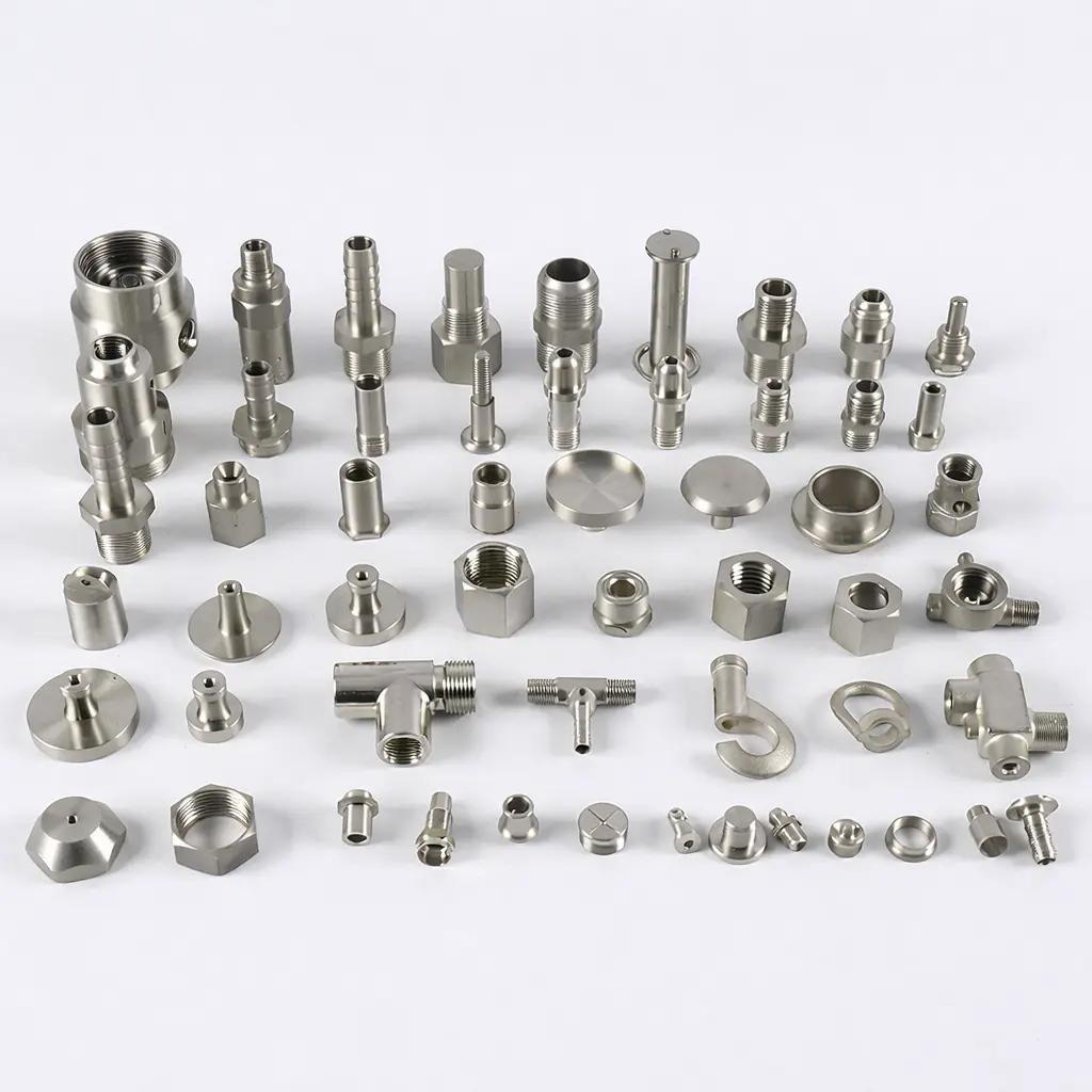

A CNC machine can produce highly accurate components, but machining accuracy is only part of the manufacturing process.
For precision mechanical parts, manufacturers also need a reliable way to verify whether the finished component actually meets the engineering drawing.
This is where Coordinate Measuring Machine, or CMM inspection, becomes valuable.
A CMM can measure the three-dimensional geometry of a component and compare the measured results with the engineering requirements. Depending on the inspection strategy, it can verify dimensions, feature locations, geometric relationships, profiles, and other critical characteristics.
For engineering teams and procurement professionals sourcing custom CNC components, understanding when CMM inspection is necessary can make it easier to define realistic quality requirements and avoid unnecessary inspection costs.
GC INDUS provides precision machining supported by engineering review, process control, and dimensional inspection. Its manufacturing workflow includes material verification, first-article inspection, in-process checks, and final validation, with CMM and other measurement equipment available for dimensional verification.
This guide explains what CMM inspection is, how it works, when it should be used, what it can verify, and how engineering teams can include CMM requirements in a CNC machining RFQ.
1. What Is CMM Inspection?
CMM stands for Coordinate Measuring Machine.
A CMM measures the location of points on a physical component within a three-dimensional coordinate system.
The machine uses a measuring probe to collect geometric data from the part.
Depending on the CMM configuration and inspection software, the system can evaluate features such as:
- Hole diameters
- Outside diameters
- Lengths
- Angles
- Positions
- Flatness
- Parallelism
- Perpendicularity
- Profiles
- Runout
- Feature-to-feature relationships
The measured data can then be compared with the requirements specified on an engineering drawing or CAD model.
This makes CMM inspection particularly useful for components where several dimensional and geometric requirements must be verified together.
2. Why CMM Inspection Matters for CNC Parts
A CNC machine follows a programmed toolpath, but several variables can affect the final result.
These may include:
- Tool wear
- Thermal expansion
- Workpiece deformation
- Fixture variation
- Material stress
- Machine condition
- Cutting forces
- Setup variation
For simple components, conventional inspection tools may be sufficient.
For more complex parts, however, checking every important feature manually can become difficult.
A CMM provides a structured way to measure multiple features within one coordinate system.
This is particularly useful when the component has:
- Complex geometry
- Multiple datums
- Tight positional requirements
- Multiple related features
- Three-dimensional profiles
- Critical assembly interfaces
3. CMM vs. Conventional Measuring Tools
CMM inspection does not replace every other inspection method.
Different measurement tools are suitable for different requirements.
Calipers
Useful for general dimensions and quick checks.
Micrometers
Suitable for precise external dimensions such as shaft diameters.
Bore Gauges
Useful for internal diameters.
Pin Gauges
Useful for checking hole sizes.
Height Gauges
Useful for dimensional and positional measurements on suitable surfaces.
Optical Measurement Systems
Useful for small features, profiles, and visual dimensional checks.
CMM
Useful for complex three-dimensional dimensional and geometric verification.
The best inspection strategy often combines several methods rather than relying exclusively on one machine.
4. When Should a CMM Be Used?
Not every CNC component requires a full CMM inspection.
CMM becomes particularly valuable when the part has critical relationships that are difficult to verify using conventional tools.
Examples include:
- Complex housings
- Precision brackets
- Multi-axis machined parts
- Medical components
- Aerospace components
- Automotive components
- Precision automation components
- Components with multiple locating holes
- Parts with complex profiles
For a simple turned spacer with one outside diameter and one overall length, a micrometer and caliper may be sufficient.
For a complex machined housing with dozens of critical features, CMM inspection can provide much more comprehensive verification.
5. CMM and Engineering Drawings
An engineering drawing tells the manufacturer what the component is supposed to be.
The CMM provides measured evidence of what the finished component actually is.
A proper inspection process therefore starts with understanding the drawing.
Important information includes:
- Nominal dimensions
- Dimensional tolerances
- Datums
- GD&T requirements
- Surface requirements
- Material specifications
- Special notes
- Critical characteristics
The inspection program can then be developed around the features that matter most.
This is one reason clear engineering documentation is essential when requesting precision CNC machining.
6. CMM and GD&T
Geometric Dimensioning and Tolerancing, or GD&T, is particularly relevant to CMM inspection.
A drawing may specify requirements for:
- Position
- Flatness
- Parallelism
- Perpendicularity
- Profile
- Circularity
- Cylindricity
- Runout
These requirements describe geometric relationships rather than simply specifying individual dimensions.
A CMM can measure the relevant features and calculate whether they fall within the specified tolerance zone.
For example, a mounting hole may have the correct diameter but still be incorrectly positioned relative to a datum.
A CMM inspection can evaluate the hole’s position relative to the defined reference system.
7. Establishing Datums
Datums provide the reference framework for many dimensional and geometric measurements.
A component may use:
Datum A → Primary reference
Datum B → Secondary reference
Datum C → Tertiary reference
The inspection setup should reproduce the intended datum structure as closely as practical.
If the inspection reference system does not correspond to the engineering requirement, the measurement results may not accurately represent functional conditions.
Therefore, CMM programming requires engineering understanding, not simply automated probing.
8. Measuring Hole Position
Hole patterns are a common reason to use CMM inspection.
Consider a plate containing twelve mounting holes.
Each hole may have:
- A specified diameter
- A specified X/Y location
- A positional tolerance
- A relationship to several datums
Checking the diameter alone does not prove that the hole pattern is correct.
The CMM can measure the actual centers of the holes and evaluate their positions relative to the drawing requirements.
This can be particularly important for components that must mate with another precision assembly.
9. Measuring Complex Profiles
Some CNC components contain surfaces that are difficult to verify using conventional tools.
Examples include:
- Curved surfaces
- Blended radii
- Complex pockets
- Freeform profiles
- Multi-axis machined surfaces
For these parts, CMM inspection can collect multiple measurement points across the surface.
The measured geometry can then be compared with the nominal CAD geometry or drawing requirement.
This provides a more comprehensive assessment than checking only a few individual dimensions.
10. CMM Inspection for CNC Milling
Milled components often contain multiple features that must maintain accurate relationships.
Examples include:
- Holes
- Pockets
- Slots
- Steps
- Planes
- Bosses
- Mounting surfaces
A complex CNC-milled housing might require verification of:
- Overall dimensions
- Hole positions
- Pocket dimensions
- Parallelism
- Perpendicularity
- Flatness
- Profile
GC INDUS provides CNC machining services for complex metal and engineering-plastic components and supports inspection requirements as part of the manufacturing workflow.
11. CMM Inspection for CNC Turning
CMM inspection can also be useful for precision turned components.
A turned shaft may require verification of:
- Diameter
- Length
- Shoulder location
- Concentric relationships
- Runout
- Groove dimensions
- Thread-related locations
For simpler turned parts, micrometers and gauges may provide efficient inspection.
For more complex rotational components, CMM inspection can provide additional geometric information.
GC INDUS supports CNC turning for precision cylindrical components and describes material verification, first-article inspection, in-process measurement, and final dimensional verification within its quality process.
12. CMM and First Article Inspection
First Article Inspection, or FAI, is often used when introducing a new component or manufacturing process.
The objective is to verify that the first production article conforms to the engineering requirements.
Depending on the project, the inspection package may include:
- Dimensional results
- Material certification
- Surface finish results
- Special-process records
- CMM reports
- Process documentation
CMM inspection can therefore form an important part of the FAI process for complex precision components.
The exact documentation required should be agreed upon before production.
13. CMM for Prototype Parts
Prototype parts do not always require comprehensive CMM inspection.
The appropriate level depends on the purpose of the prototype.
If the prototype is mainly being used to evaluate:
- Appearance
- Basic dimensions
- General fit
a full CMM report may not be necessary.
If the prototype is being used to validate:
- Precision assembly
- Critical interfaces
- Functional dimensions
- Complex geometry
then CMM inspection may be worthwhile.
The inspection plan should match the engineering objective.
14. CMM for Production Parts
Production inspection presents a different challenge.
The manufacturer needs to balance:
Measurement coverage + inspection time + production volume + risk
For high-volume production, inspecting every dimension on every component with a CMM may not always be necessary.
Instead, a production quality plan may combine:
- First article inspection
- In-process checks
- Statistical process monitoring
- Gauge inspection
- Periodic CMM verification
- Final inspection
The appropriate approach depends on the part’s risk and customer requirements.
15. CMM and Process Control
CMM inspection should not only be used to identify bad parts after machining.
Measurement data can also support process control.
Suppose a critical bore gradually moves toward the upper tolerance limit.
If measurements are collected consistently, the trend can be detected before the feature becomes out of tolerance.
The manufacturing team can then investigate:
- Tool wear
- Fixture movement
- Machine thermal conditions
- Cutting parameters
- Process variation
This makes inspection part of a feedback loop rather than simply a final acceptance step.
16. CMM and Tool Wear
Cutting tools gradually wear during production.
As tool geometry changes, dimensions can also change.
For critical features, inspection data can help identify this trend.
A manufacturer may establish measurement intervals based on:
- Material
- Tool type
- Cutting conditions
- Production volume
- Historical tool life
- Feature criticality
This can help prevent unexpected dimensional drift.
17. Temperature and Measurement Accuracy
Temperature can affect both machining and measurement.
Metal components expand and contract with temperature.
For extremely tight tolerances, environmental conditions can therefore become important.
This is one reason high-precision inspection environments may use controlled temperature conditions.
For less demanding components, normal shop-floor inspection may be adequate.
The required measurement environment should correspond to the tolerance and risk of the component.
18. CMM Programming
CMM inspection requires an inspection program.
The program generally defines:
- Part alignment
- Datum establishment
- Feature identification
- Measurement strategy
- Tolerance evaluation
- Reporting requirements
The inspection program should reflect the engineering drawing.
For recurring production, a validated CMM program can improve inspection consistency between production batches.
19. CAD-Based CMM Inspection
Modern CMM systems can use CAD data to assist with inspection programming and reporting.
This can be especially useful for complex components.
The CAD model provides the nominal geometry, while the CMM captures the actual manufactured geometry.
The inspection system can then compare:
Nominal Geometry ↔ Measured Geometry
This can make it easier to identify dimensional deviations and geometric trends.
However, the CAD model should not automatically replace the engineering drawing.
The drawing remains important for defining:
- Tolerances
- Datums
- Surface requirements
- Material
- Special notes
- Acceptance criteria
20. CMM Reports
A CMM inspection report typically presents measured results against nominal requirements.
Depending on the project, the report may include:
- Feature number
- Nominal dimension
- Actual measurement
- Upper tolerance
- Lower tolerance
- Deviation
- Pass/fail status
Some reports also include graphical representations of the measured geometry.
Before production, the customer and manufacturer should agree on the required report format.
21. Inspection Equipment Should Match the Tolerance
One of the most important quality principles is:
The measurement system must be capable of verifying the requirement.
For example, if a feature has a relatively broad tolerance, a basic calibrated measuring instrument may be sufficient.
For complex geometric requirements, a CMM may be appropriate.
For surface roughness, a profilometer may be necessary.
For material composition, a material verification method such as XRF may be appropriate depending on the material and specification.
Inspection should therefore be selected based on the actual engineering requirement.
22. CMM Inspection and Surface Finish
CMM primarily evaluates dimensional and geometric characteristics.
It does not replace specialized surface-finish measurement.
If a drawing specifies:
Ra 0.8 μm
the manufacturer needs an appropriate surface roughness measurement method.
Likewise, if a part requires anodizing, plating, passivation, polishing, or heat treatment, those requirements need their own verification methods.
GC INDUS offers multiple surface treatment options including anodizing, plating, polishing, passivation, heat treatment, powder coating, and other finishing processes.
23. Material Verification and CMM Inspection
Dimensional inspection confirms geometry.
It does not prove that the material is correct.
A complete quality process may therefore require both:
Material Verification + Dimensional Verification
Depending on the project, material documentation can include:
- Mill certificates
- Material test reports
- Heat numbers
- Traceability information
GC INDUS’s precision machining service describes material certification and traceability as part of its quality workflow.
24. CMM and Complex Materials
Material characteristics can influence dimensional stability.
For example:
Aluminum may be sensitive to thermal expansion and thin-wall deformation.
Stainless steel may generate higher cutting forces.
Titanium may require specialized machining strategies.
Engineering plastics can have significant thermal expansion compared with metals.
Therefore, inspection requirements should consider both geometry and material behavior.
GC INDUS supports a broad range of material options and evaluates material, manufacturing process, cost, and finishing compatibility during engineering review.
25. When CMM Inspection May Not Be Necessary
CMM inspection is powerful, but it is not automatically required for every part.
It may be unnecessary when:
- The component is simple
- Tolerances are relatively broad
- Conventional gauges can verify the requirements
- Production risk is low
- The customer does not require a CMM report
For example, a simple washer-like component may be efficiently inspected using conventional gauges.
Using advanced inspection equipment for every feature can add time without providing meaningful additional quality assurance.
26. When Full CMM Inspection Makes Sense
A comprehensive CMM inspection can be justified when:
- The part has complex geometry
- Several GD&T features are critical
- The component has tight positional requirements
- Multiple features interact functionally
- The part is used in a safety-critical application
- The customer requires dimensional reports
- First article validation is required
- Supplier qualification requires documented inspection
The inspection strategy should always be proportional to the risk.
27. How CMM Inspection Can Reduce Manufacturing Risk
CMM inspection does more than produce a report.
It can help identify problems such as:
- Incorrect datum interpretation
- Fixture movement
- Tool wear
- Machine drift
- Thermal effects
- Process instability
- Drawing interpretation issues
When inspection data is fed back into engineering and production, the manufacturing process can become more controlled.
This is why quality should be treated as a system rather than a final inspection event.
28. How to Specify CMM Requirements in an RFQ
If your project requires CMM inspection, include the requirement in the RFQ.
Specify:
1. Which features are critical
Do not assume the supplier knows which dimensions matter most.
2. Required inspection frequency
Prototype, first article, sample quantity, periodic production inspection, or 100% inspection.
3. Required report
Full dimensional report, selected-feature report, or customer-specific format.
4. Drawing revision
The inspection must correspond to the correct drawing revision.
5. GD&T requirements
Identify relevant datums and geometric tolerances.
6. Material documentation
Specify whether MTR/MTC or traceability documents are required.
7. Surface requirements
Identify Ra, coating thickness, treatment, or other finishing requirements.
Clear requirements reduce misunderstandings during quotation and production.
29. Common CMM Inspection Mistakes
Mistake 1: Measuring Without Understanding the Drawing
The machine may collect data, but the result may not represent the actual functional requirement.
Mistake 2: Ignoring Datums
A measurement without the correct reference structure can produce misleading conclusions.
Mistake 3: Using CMM for Everything
Some features are faster and more efficiently checked with gauges or micrometers.
Mistake 4: Inspecting Too Late
Waiting until final inspection to identify process drift can increase scrap.
Mistake 5: Ignoring Temperature
Very tight tolerances may require controlled measurement conditions.
Mistake 6: Measuring the Wrong Revision
Always verify that the CMM program and inspection report correspond to the latest approved drawing.
Mistake 7: Treating Inspection as Separate From Manufacturing
The best results come when inspection data is used to improve the manufacturing process.
30. Frequently Asked Questions
1. What is CMM inspection?
CMM inspection uses a coordinate measuring machine to measure three-dimensional features of a physical component and compare them with engineering requirements.
2. Do all CNC parts require CMM inspection?
No. The appropriate inspection method depends on part complexity, tolerance, risk, production volume, and customer requirements.
3. What can a CMM measure?
A CMM can measure many dimensional and geometric characteristics, including sizes, positions, angles, profiles, flatness, perpendicularity, parallelism, and runout.
4. Is CMM better than a micrometer?
Neither is universally better. A micrometer is highly effective for certain simple dimensional measurements, while CMM is more suitable for complex three-dimensional measurement and geometric relationships.
5. Can CMM inspect GD&T?
Yes. CMM systems can evaluate many GD&T requirements when the inspection setup, datum structure, software, and measurement strategy are appropriate.
6. Is CMM inspection necessary for prototypes?
Not always. It depends on what the prototype is intended to validate and which dimensions are critical.
7. Can CMM inspection reduce production problems?
Yes. Consistent measurement can help identify dimensional drift, tool wear, fixture problems, and process variation before they result in large quantities of nonconforming parts.
8. What should I provide when requesting CMM inspection?
Provide the latest engineering drawing, CAD model where applicable, material specification, critical tolerances, GD&T requirements, surface requirements, quantity, and desired inspection report format.
Conclusion
CMM inspection is an important tool for verifying complex CNC machined components, but it should be used as part of a broader quality system.
The best inspection strategy combines:
Engineering Requirements + Process Control + Appropriate Measurement + Documentation
For simple components, conventional gauges may be sufficient.
For complex precision components, CMM inspection can provide a much more comprehensive view of dimensional and geometric accuracy.
Most importantly, inspection should not be treated as something that happens only after machining is finished.
The strongest manufacturing workflows connect:
DFM → Process Planning → Controlled Machining → In-Process Inspection → Final Verification
GC INDUS follows an engineering-led manufacturing approach in which geometry, material, process, and quality controls are reviewed throughout the production workflow. Its current manufacturing information highlights engineering review, process planning, controlled production, inspection, and global delivery as connected stages.
If your component has tight tolerances, complex geometry, critical hole patterns, demanding GD&T requirements, or customer-specific inspection documentation, the inspection strategy should be discussed before production begins.
Send your CAD file and engineering drawing to the GC INDUS engineering team for review.


