
Book Appointment Now

GC INDUS / MANUFACTURING KNOWLEDGE
How Insert Molding Precision Manufacturing Merges Materials

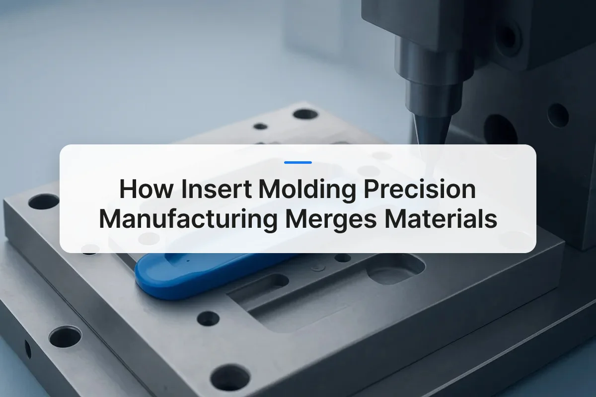
Insert molding precision manufacturing is a process where pre-formed inserts, typically metal, ceramic, or another rigid material, are placed into an injection mold cavity before plastic is injected around them, creating a single, structurally unified component. This eliminates secondary assembly steps, reduces part count, and improves dimensional consistency. It is widely used in aerospace, medical, automotive, and electronics applications where tight tolerances and bond integrity between dissimilar materials are non-negotiable.
What Is Insert Molding in Precision Manufacturing
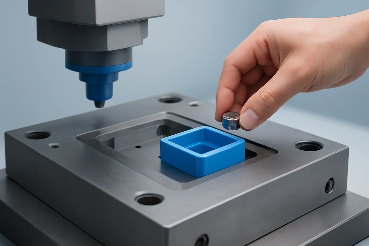
Insert molding places a pre-formed solid insert inside a mold cavity, then injects polymer around it to produce one monolithic part in a single cycle.
The insert, typically metal, ceramic, or a structural composite, becomes permanently encapsulated. No adhesive, no fastener, no secondary assembly step. The result is a component whose mechanical properties come from both materials acting together, not from a joint between them.
The “precision” qualifier matters here. Not every insert molding operation qualifies. The process earns that label only when insert placement tolerances, wall thickness uniformity around the insert, and bond-line integrity are held to tight dimensional specifications throughout the run, not just on the first shot.
How Insert Molding Differs from Overmolding and Standard Injection Molding
Standard injection molding fills a cavity with a single material, no insert present. Overmolding molds a second material over a substrate that was already molded in a prior cycle. Insert molding is distinct from both: the insert is a finished, non-plastic component placed into the tool before the first shot of polymer.
Precision requirements differ across all three. Standard molding controls cavity fill and shrinkage. Overmolding adds bond-layer adhesion between two polymer surfaces. Insert molding demands all of that plus positional accuracy of a rigid, often metallic insert, which must not shift under injection pressure or thermal expansion during the cycle.
Material Combinations Available in Insert Molding
Metal-to-plastic bonds are the most common pairing in insert molding precision manufacturing. Threaded brass inserts encapsulated in nylon or polycarbonate housings are a standard example: the brass provides pull-out strength and thread durability that plastic alone cannot sustain, while the nylon reduces weight and allows complex geometry.
Ceramic-to-plastic combinations address different requirements. Alumina or zirconia inserts bonded within a polymer body appear in applications needing electrical insulation at high temperatures, medical ablation tools and industrial sensors are typical cases.
Composite-to-plastic pairings, carbon fiber or glass-fiber preforms encapsulated in thermoplastic, serve structural aerospace and automotive components where the goal is stiffness-to-weight ratio rather than conductivity or thread strength. Each material pairing changes the mold design, the injection parameters, and the inspection criteria required to confirm bond integrity.
How the Insert Molding Precision Manufacturing Process Works Step by Step
Insert molding precision manufacturing follows a six-stage sequence: prepare the insert, place it in the mold, clamp, inject polymer, cool, then eject and inspect.
Each stage applies specific controls that determine whether the finished part meets tolerance. A breakdown at any point—insert contamination, placement drift, incorrect fill pressure—compounds through every stage that follows.
Stage 1: Insert Preparation and Pre-Treatment
Metal inserts arrive at the mold station after cleaning, knurling, or surface coating. Knurling cuts mechanical grip patterns into the insert surface so the injected plastic bonds to geometry rather than relying on adhesion alone. Contamination from oils or oxides prevents bonding, so cleaning is a process control step, not a housekeeping task.
Pre-treatment steps vary by material and application. Common preparation methods include:
- Ultrasonic cleaning to remove machining oils and surface oxides from metal inserts before placement
- Knurling or cross-hatching to create mechanical interlock geometry on the insert surface
- Plasma or chemical etching for ceramic inserts where surface energy must be raised to promote polymer adhesion
- Pre-heating of metal inserts in high-volume runs to reduce thermal shock at the polymer-metal interface during injection
- Coating or plating where corrosion resistance or electrical conductivity at the bond interface is required
Stage 2: Placement, Clamp, and Injection
Operators or robotic arms seat the insert onto locating pins inside the mold cavity. Those pins and the surrounding nest geometry control placement accuracy—if an insert drifts even a fraction of a millimeter off-center, the plastic wall thickness around it becomes uneven, weakening the bond and potentially causing part failure under load.
Once the mold clamps, the injection parameters diverge from standard molding. Gate location relative to the insert matters: injecting directly toward a metal insert creates a pressure wave that can shift it or generate residual stress in the surrounding polymer as it cools. Fill pressure and cooling rate are tuned together to minimize that stress concentration.
Stage 3: Cooling, Ejection, and Inspection
Cooling time is managed carefully because metal and plastic shed heat at different rates. Uneven solidification creates internal stress at the interface—visible later as cracking or delamination in service.
After ejection, each part enters inspection. Dimensional checks confirm the insert sits within positional tolerance; pull or torque tests verify bond strength meets specification.
Special Considerations for Injection Mold Inserts During Production
Tooling lead time typically runs longer than production startup time—mold design and fabrication dominate the schedule before a single part runs. Low-volume prototype runs often use manual insert placement, which keeps tooling costs lower but slows cycle time. High-volume series production justifies automated placement systems that reduce cycle time and eliminate human placement variation.
GC INDUS applies full inspection protocols at ejection, including dimensional verification and bond integrity checks, so insert-molded parts ship with documented conformance rather than assumed quality.
Advantages and Disadvantages of Insert Molding Versus Traditional Assembly
Insert molding outperforms post-mold assembly on structural integrity and per-unit labor, but carries higher upfront tooling cost and less design flexibility.
Where Insert Molding Has the Edge
Consolidating multiple parts into a single molded component eliminates the tolerance stack-up that accumulates across multi-part assemblies. Fewer discrete parts also mean fewer assembly operations, which directly cuts labor time and reduces the risk of handling contamination—a critical factor in medical device and electronics manufacturing.
Encapsulating an insert in plastic produces measurably better pull-out and torque resistance than press-fit or adhesive-bonded alternatives. The plastic flows around the insert geometry during molding, creating mechanical interlock that adhesives and interference fits cannot reliably replicate under cyclic loading or thermal cycling.
Where Insert Molding Falls Short
Tooling a mold costs significantly more than building simple assembly fixtures. Insert placement—particularly manual loading—adds cycle time to every shot, and that overhead compounds at high cavitation counts. Design changes are the bigger constraint: modifying a bonded or press-fit assembly process is a procedure update, while changing an encapsulated feature requires mold rework or a new tool entirely.
The Cost-Benefit Logic at Scale
Insert molding precision manufacturing shifts cost structure from recurring per-unit assembly labor toward a one-time tooling investment. At low volumes, that upfront spend rarely pays back. As volume grows, the per-unit labor savings accumulate and the tooling cost amortizes—making insert molding progressively more favorable the longer a design stays stable.
When Traditional Assembly Still Wins
Post-mold assembly remains the better choice for very low production volumes, products in active design iteration, or applications where the insert must be field-replaceable. A threaded brass insert bonded into a housing cannot be swapped in the field; one assembled with a retaining clip can.
Common Applications and Industries That Rely on Insert Molding
Insert molding delivers the most value in medical devices, automotive assemblies, electronics connectors, and industrial tools—wherever a single bonded component must outperform a mechanically joined one.
How Different Industries Implement Insert Molding in Real-World Production
Medical devices depend on insert molding precision manufacturing for parts where adhesive joints are a liability. Encapsulated metal electrodes, cannula hubs, and sensor housings benefit from a direct polymer-to-metal bond that survives repeated sterilization cycles—autoclaving, gamma radiation, and EtO—without delaminating. Adhesive joints can fail under those thermal and chemical stresses; a molded encapsulation does not.
Automotive and aerospace engineers use threaded metal inserts molded into polymer housings to create vibration-resistant fastening points that hold torque specifications over years of mechanical cycling. Connector bodies with embedded electrical contacts and lightweight structural brackets—where metal reinforcement is placed only where load demands it—are standard insert-molded components in both sectors.
Electronics and connector manufacturers rely on insert molding to hold pin positions in plastic connector bodies within fractions of a millimeter. Antenna inserts and EMI shielding elements require that dimensional repeatability because even a small shift in insert position changes impedance or shielding effectiveness.
Consumer and industrial products use insert molding to bond ergonomic polymer grips over metal cores in tool handles, knobs, and control levers. The molded bond distributes stress across the entire interface rather than concentrating it at a glue line—which is why insert-molded grips outlast adhesive-bonded alternatives in long-term fatigue testing. GC INDUS produces parts across all four of these sectors, holding tolerances to ±0.001mm to ensure insert position is correct from the first shot.
Design and Quality Considerations for Precision Insert Molding
Precision insert molding succeeds or fails at the design stage, wall thickness, gate placement, and tolerance budgeting determine whether finished parts hold spec or generate scrap.
DFM Best Practices Specific to Insert Molding Constraints
Minimum wall thickness around a metal insert is the first constraint to resolve. Too thin, and the polymer cannot absorb thermal stress during cooling, causing sink marks or cracking at the insert boundary. Too thick, and extended cooling time creates its own sink risk on the outer surface.
Draft angles on the insert geometry matter as much as they do on the mold cavity itself. Without adequate draft, typically 1° to 3° depending on insert geometry, the insert can resist ejection and shift under the force applied, distorting the bond interface.
Gate placement directly affects weld line location. Positioning gates so that flow fronts meet away from the insert-polymer interface prevents the weakened bond that weld lines create. A flow simulation run before tool steel is cut identifies problem zones before they become defects.
Quality Control Standards and Tolerances for Precision Insert Molding
Tolerance management in insert molding precision manufacturing requires budgeting three independent variables: insert positional tolerance, mold cavity tolerance, and polymer shrinkage. Treating them as a single combined spec is a common error, each source of variation must be allocated its own budget so the stack-up stays within the final part drawing.
Three defect mechanisms account for most field failures. Insert shift during injection traces back to insufficient fixturing in the mold. Delamination at the bond interface usually signals surface contamination on the insert or a material incompatibility between the polymer and the substrate. Sink marks point to wall sections too thick relative to the cooling cycle.
Post-mold inspection addresses these risks directly. Dimensional checks confirm insert position within the molded part. Pull-force and torque testing verify bond integrity under the mechanical loads the part will see in service. ISO 9001 process documentation, which GC INDUS maintains across its injection molding operations, ties each inspection record to a specific production run, so any defect can be traced to its root cause and corrected before the next batch ships.
Common Defects and How to Prevent Them
Understanding the root causes of insert molding defects allows engineers to design them out before production begins. The most frequently encountered issues and their primary countermeasures are:
- Insert shift during injection: Caused by insufficient locating pin engagement or excessive injection pressure directed at the insert face. Resolved by redesigning the nest geometry and adjusting gate position.
- Delamination at the bond interface: Typically caused by surface contamination or a mismatch in thermal expansion coefficients between the insert and polymer. Resolved through rigorous pre-treatment and material compatibility review at the design stage.
- Sink marks on outer surfaces: Result from wall sections that are too thick relative to the cooling cycle. Resolved by reducing wall thickness or extending cooling time with conformal cooling channels.
- Weld line weakness near the insert: Occurs when flow fronts meet at the insert boundary. Resolved by repositioning gates so flow fronts converge away from the insert-polymer interface.
- Cracking under thermal cycling: Caused by residual stress locked in during cooling. Resolved by pre-heating inserts and optimizing pack pressure to reduce stress concentration at the interface.
Frequently Asked Questions
What is the difference between insert molding and overmolding?
Insert molding places a pre-made component—typically metal—into the mold before plastic is injected, enclosing it in a single shot. Overmolding, by contrast, molds a second layer of plastic over an already-molded plastic substrate in a separate shot. The key distinction is substrate type and sequence: insert molding bonds plastic to a non-plastic insert in one step, while overmolding bonds plastic to plastic across two steps.
What types of inserts are most commonly used in precision insert molding?
Threaded metal inserts—usually brass or stainless steel—are the most common, followed by electrical contacts, pins, bushings, and studs. Aluminum inserts appear frequently in lightweight structural applications, while ceramic or glass-fiber components are used where thermal or electrical insulation is required. The insert material must withstand the injection pressure and temperature without deforming or shifting during the shot.
How does insert placement accuracy affect the final part quality?
Inaccurate insert placement causes misaligned features, wall thickness variation, and stress concentrations that can crack the surrounding plastic under load. In medical and automotive applications, a positional error of even a fraction of a millimeter can push a part out of specification and trigger a full-lot rejection. Precision fixturing and in-mold sensors are the primary controls used to hold placement repeatability across a production run.
At what production volume does insert molding become more cost-effective than post-mold assembly?
Insert molding typically becomes more cost-effective than post-mold assembly once tooling costs are amortized across a sufficiently large run. Below that threshold, manual assembly of separate components can be cheaper because it avoids mold investment. Above it, the elimination of secondary assembly labor, adhesives, and fasteners reduces per-unit cost—and the reduction in assembly-related defects adds further value in quality-critical applications.
Which polymer materials are best suited for insert molding precision manufacturing?
The best polymer choice depends on the insert material, the service environment, and the required mechanical properties. Nylon and polycarbonate are widely used with metal inserts because they flow well around complex insert geometry and provide good mechanical interlock after cooling. PEEK and PPS are preferred in high-temperature or chemically aggressive environments. The key selection criterion is matching the polymer’s thermal expansion coefficient as closely as possible to the insert material to minimize interface stress during thermal cycling.
Conclusion
Insert molding delivers measurable advantages—reduced part count, tighter structural integration, and fewer assembly steps—but only when the process is engineered correctly from the start. Insert geometry, material compatibility, and placement tolerances must all be resolved at the design stage, not corrected after tooling is cut.
For engineers sourcing insert-molded components, the practical next step is to submit your part drawing with insert specifications for a tolerance and material compatibility review before committing to a mold design. GC INDUS accepts STEP and IGES files and can provide a fast quote that covers insert molding alongside CNC machining and finishing—so you get a single-source assessment rather than fragmented supplier feedback.
Recommended Articles
Explore more from our content library:


