
Book Appointment Now

GC INDUS / MANUFACTURING KNOWLEDGE
How Reverse Engineering Precision Manufacturing Works

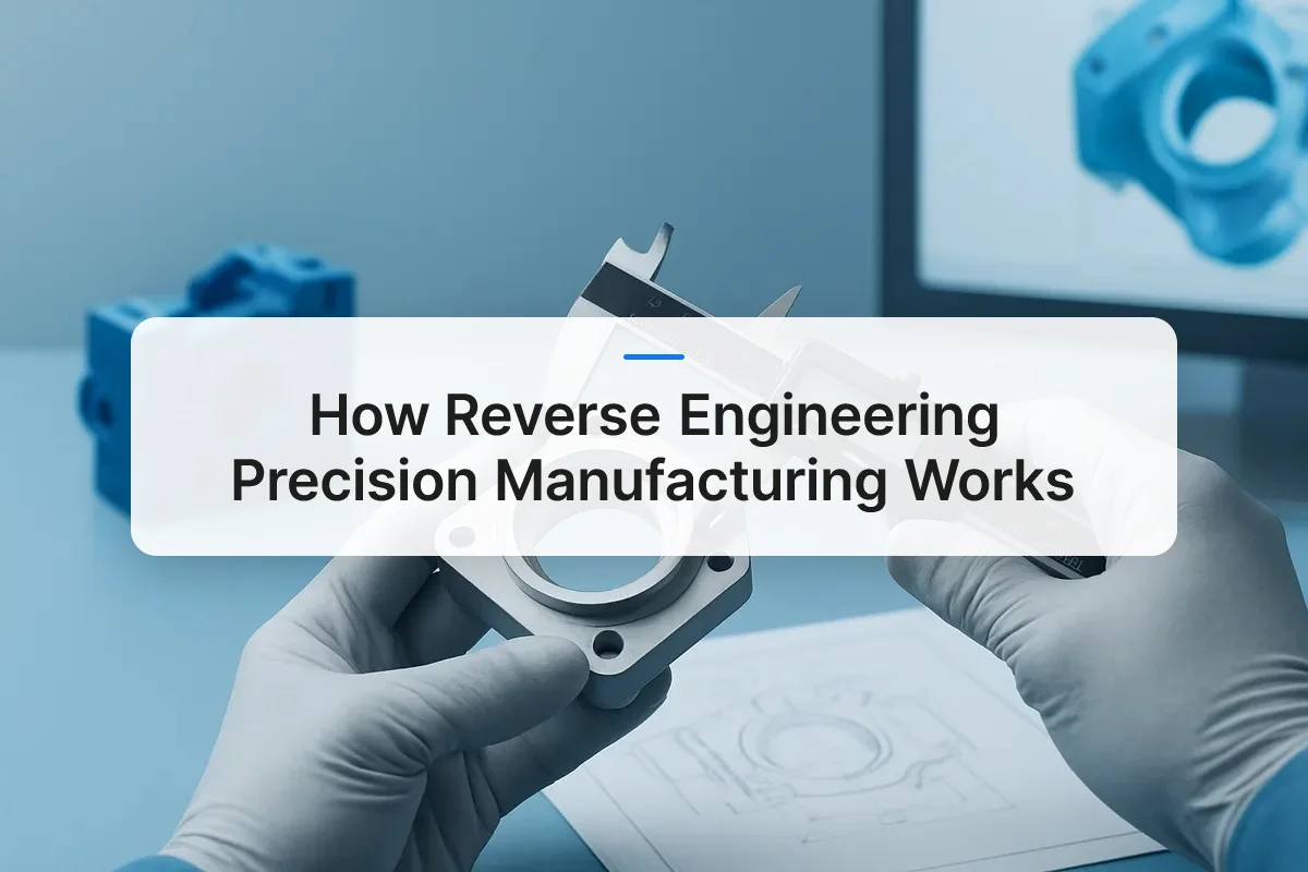
Understanding reverse engineering precision manufacturing is essential for any engineer tasked with reproducing obsolete components, validating manufactured parts, or accelerating product development without original design documentation. Reverse engineering in precision manufacturing is the process of capturing an existing physical part’s geometry, dimensions, and material properties to recreate accurate CAD models and production-ready drawings. When paired with tight-tolerance measurement tools, it bridges the gap between a physical object and a manufacturable digital twin.
What Reverse Engineering Precision Manufacturing Actually Means
Reverse engineering in precision manufacturing converts a physical part into verified CAD data — geometry, tolerances, surface finish, and material spec — where no drawing exists. This is particularly relevant for reverse engineering precision manufacturing workflows that must serve as the sole source of truth for downstream production.
The process produces a complete technical record: a dimensioned CAD model, GD&T callouts, surface finish requirements, and material identification. That record then drives CNC programming, toolpath selection, and quality inspection — the same inputs any new-design part would carry from day one.
This is distinct from inspection. Inspection checks a finished part against a drawing that already exists. Reverse engineering creates the drawing when none is available, typically for obsolete components, legacy machinery, or parts whose original documentation was lost or never produced.
How Precision Engineering Differs from Standard Reverse Engineering
Consumer-product reverse engineering tolerates millimeter-level approximation. Precision manufacturing does not. A measurement error of even a few microns can propagate directly into scrap or a non-conforming part, particularly in medical device or aerospace applications where tolerances routinely reach ±0.001mm.
That sensitivity makes the measurement phase the most critical step. Coordinate measuring machines (CMMs), laser scanners, and structured-light systems must capture geometry at a resolution that matches the required tolerance band, not merely the visible shape of the part.
Is It Legal to Reverse Engineer Components?
Reverse engineering is generally lawful when applied to parts you own, for purposes such as interoperability or legacy replacement. U.S. courts have consistently recognized this principle under trade secret law, provided the method of discovery is independent analysis rather than misappropriation.
Patent and trade secret boundaries still apply. If a manufacturing process, not just the part geometry, is protected, replicating it can create liability. This article explains the general principle; consult legal counsel before proceeding with any component where IP ownership is unclear.
How the Reverse Engineering Process Works in Precision Manufacturing
Reverse engineering in precision manufacturing follows five sequential stages: physical capture, data processing, mesh refinement, CAD reconstruction, and tolerance verification.
Each stage builds on the last, and errors introduced early — a missed surface, a vibration artifact during scanning — compound through the workflow. Understanding what each stage demands helps engineers allocate time, budget, and review effort correctly. When considering reverse engineering precision manufacturing, this point stands out as the most common source of project overruns.
The Core Workflow: From Physical Part to Verified CAD
The process begins with physical measurement or scanning of the original component. The output is either a point cloud (from laser or structured-light scanners) or discrete coordinate data (from contact CMM probing). That raw data is then processed into a mesh — a triangulated surface that approximates the part geometry.
Mesh processing is where surface noise, gaps from occluded features, and scan overlap errors get resolved. The cleaned mesh feeds into CAD reconstruction, where engineers rebuild parametric geometry — curves, planes, and solids — that can be modified and manufactured. The final stage compares the reconstructed CAD model against the original captured geometry to verify that critical features fall within the required tolerance band.
Human judgment is irreplaceable at the reconstruction stage. Worn or damaged surfaces must be interpreted as design intent, not captured as-worn geometry. Ambiguous radii, blended transitions, and functional mating surfaces all require an engineer to decide what the part should be, not just what the scan shows. Material identification — matching hardness, alloy grade, or surface treatment — adds another layer that no scanner resolves automatically.
What Accuracy Tolerances Can Different Techniques Achieve?
Contact CMM probing resolves features at sub-micron levels because a calibrated ruby probe touches the surface directly, eliminating optical distortion. Probe diameter and stylus deflection are the primary error sources, both of which are measurable and compensated in modern CMM software.
Structured-light and laser scanning achieve tighter results than photogrammetry alone. Spot size, focal distance, and environmental vibration all affect resolution — a scanner on an unsupported bench in a busy shop floor will produce noisier data than the same device on a vibration-isolated table. For parts requiring tolerances at ±0.001mm, CMM verification after scan-based reconstruction is standard practice, not optional.
How Long Does a Reverse Engineering Project Take from Scan to CAD?
Project duration depends on four variables: part complexity, feature count, surface accessibility, and the required tolerance band.
A simple turned component with cylindrical features and two datum surfaces takes far less time than a multi-cavity die with internal cooling channels and compound draft angles. Inaccessible surfaces — internal bores, undercuts, blind pockets — require repositioning, fixturing, or CT scanning, each adding time. A tighter tolerance band demands more scan passes, denser point clouds, and longer verification cycles.
Use those four variables as a scoping framework: estimate complexity first, then identify inaccessible features, then set the tolerance target. That sequence surfaces the real schedule drivers before a project starts rather than mid-way through reconstruction. For those exploring reverse engineering precision manufacturing, this scoping discipline is what separates on-time projects from costly overruns.
Reverse Engineering Methods and Tools Compared
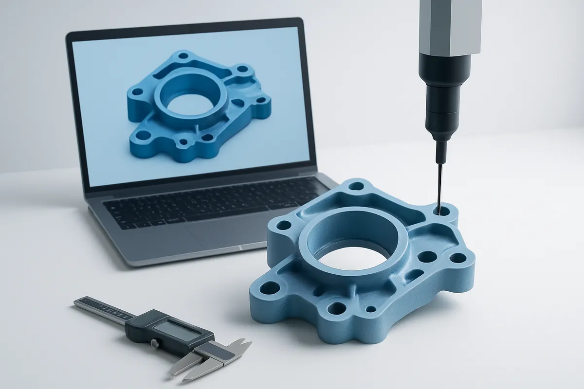
Three capture methods dominate reverse engineering in precision manufacturing: 3D scanning, manual measurement, and CMM probing — each suited to different part types and tolerance requirements.
How Do 3D Scanning, Manual Measurement, and CAD Reconstruction Compare?
Manual measurement — calipers, micrometers, height gauges — is the budget-friendly starting point. It works well on simple prismatic parts with accessible surfaces, but it is labor-intensive and cannot reliably capture freeform curves or deep internal features.
Structured-light and laser-line scanners occupy the mid-range tier. They capture freeform surfaces and complex external geometry quickly, generating dense point clouds that translate directly into surface models. The limitation: neither method reaches deep bores, internal channels, or enclosed cavities without disassembly.
CMM probing sits between the two in terms of geometry coverage. It excels on prismatic features — flat faces, bored holes, datum planes — where discrete touch-point measurements deliver high accuracy. On organic or sculpted geometry, however, CMM probing is slow because each point requires a separate probe contact.
Industrial CT scanning is the only non-destructive method for capturing internal geometry. It maps internal channels, wall thicknesses, and hidden assembly interfaces without cutting the part open — critical for complex castings, multi-material assemblies, or high-value components where destructive inspection is not an option. CT is a premium-tier investment, reserved for parts where internal geometry directly affects function or where failure risk is high.
| Method | Best For | Key Limitation | Cost Tier |
|---|---|---|---|
| Manual measurement | Simple prismatic parts | Cannot capture freeform or internal features | Budget-friendly |
| Laser / structured-light scan | Freeform external surfaces | Cannot reach deep bores or enclosed cavities | Mid-range |
| CMM probing | Prismatic features, datums | Slow on organic geometry | Mid-range |
| Industrial CT scanning | Internal geometry, complex castings | Premium cost; slower throughput | Premium |
Which Reverse Engineering Software Criteria Matter Most?
Software selection shapes how usable your captured data becomes. Prioritize native CAD format output — STEP and IGES files integrate directly into downstream design and CAM environments without conversion errors.
Deviation analysis overlays let engineers compare the reconstructed model against the original scan mesh, flagging where the CAD surface drifts from measured reality. Feature recognition automation speeds up the conversion of raw point clouds into editable solid geometry, reducing manual modeling time on prismatic features. Confirm that any platform you evaluate connects cleanly to your CAM environment before committing — format incompatibility at that stage adds rework that reverse engineering precision manufacturing is specifically meant to eliminate.
Key Criteria for Evaluating Reverse Engineering Software
When selecting software for a precision manufacturing workflow, the following criteria should be evaluated systematically:
- Native CAD output formats: STEP, IGES, and Parasolid ensure compatibility with downstream CNC and CAM environments without lossy conversion.
- Deviation analysis tools: Color-map overlays that compare reconstructed CAD against the original scan mesh, highlighting out-of-tolerance regions at a glance.
- Automated feature recognition: Identifies planes, bores, slots, and cylinders directly from point cloud data, reducing manual modeling time on prismatic geometry.
- Mesh repair and noise filtering: Fills gaps from occluded surfaces, removes scan artifacts, and smooths overlap regions without distorting critical geometry.
- GD&T annotation support: Allows engineers to apply geometric dimensioning and tolerancing callouts directly within the reconstruction environment.
- CAM integration: Direct links to machining software reduce file-transfer steps and eliminate format-conversion errors before toolpath generation.
When to Use Reverse Engineering Instead of Designing from Scratch
Reverse engineering is the right choice when no original drawings exist, a supplier has discontinued a component, or mating geometry drives the design constraint.
The clearest cases for reverse engineering precision manufacturing work share one trait: the physical part carries information that no longer exists anywhere else. Obsolete components with no surviving CAD files, worn tooling that must be replicated to match existing fixtures, and legacy assembly interfaces where the mating geometry is the hard constraint all fall into this category. When a supplier discontinues a critical component, waiting months for a new design cycle is rarely an option.
Cost-Benefit Tradeoffs Between Reverse Engineering and New Design
Reverse engineering front-loads cost in measurement and 3D model reconstruction, but it eliminates design iteration cycles. New design front-loads engineering time but can yield geometry optimized for current materials and manufacturing processes. The crossover point depends on part complexity and production volume — for a single replacement part, reconstruction almost always costs less than a full design effort; for a high-volume production run of a simple component, a clean-sheet design may pay back faster.
Three conditions make reverse engineering a poor choice:
- Highly complex multi-material assemblies that require CT scanning to resolve internal geometry are expensive to reconstruct when the part itself has low replacement value.
- Parts with extensive wear can obscure the original geometry so thoroughly that the reconstructed model reflects the degraded state rather than the nominal specification.
- Modern off-the-shelf equivalents that exist at lower total cost make reverse engineering an unnecessary expense that adds no value to the production chain.
That third scenario connects directly to a trap engineers must watch for: reverse engineering a worn part replicates wear, not the original design intent. The resulting CAD model captures the as-built, as-worn state. Engineers must decide deliberately whether to reconstruct nominal geometry — using symmetry, standard radii, and engineering judgment to infer original dimensions — or to capture the as-worn state for a specific fit purpose. That choice directly affects downstream performance and whether the manufactured replacement will match the original specification or simply match the degraded part.
Real-World Applications of Reverse Engineering in Precision Manufacturing
Reverse engineering precision manufacturing projects succeed across aerospace, medical, automotive, and industrial sectors when scan accuracy matches the required part tolerance.
In aerospace MRO, engineers reproduce out-of-production structural brackets where original drawings no longer exist. A physical part is scanned, a CAD model is reconstructed, and the component is re-machined to the same geometry — often to tolerances tighter than the original drawing specified, because modern CNC equipment can hold what older processes could not.
Medical device replication demands the same discipline. Matching implant geometry for mechanical compatibility requires distinguishing functional surfaces — bearing faces, fixation holes — from cosmetic ones. Treating every surface as equally critical wastes time and introduces unnecessary rework.
Automotive tooling recovery applies the same logic to press dies worn beyond specification. Scanning the worn tool, modeling the nominal geometry, and re-machining restores production capacity without sourcing a replacement die from a supplier who may no longer stock it. Industrial equipment maintenance follows the same path for obsolete gearbox components where the original manufacturer has discontinued the part.
Project success consistently depends on three factors: scan accuracy matched to part tolerance, clear functional-versus-cosmetic surface classification, and a final verification step where the machined part is re-scanned and compared against the reconstructed CAD.
Will AI and Automation Change How Reverse Engineering Is Done?
AI tools are already reducing manual CAD reconstruction time on prismatic parts through automated feature recognition — software identifies planes, bores, and slots directly from point cloud data rather than requiring an engineer to trace each feature by hand.
Machine-learning deviation analysis can flag systematic errors across a scan — a consistent undercut on one face, for example — rather than requiring point-by-point review. These tools are useful but not yet mature enough to replace engineer judgment on complex freeform geometry.
Reverse engineering also doubles as a production quality assurance tool. When a machined part’s scan is overlaid against its nominal CAD, the same workflow that reconstructed the original geometry now confirms the finished part meets specification. GC INDUS applies full inspection protocols at this stage, holding tolerances to ±0.001mm and validating every functional surface before a component ships — the same quality discipline that underpins its ISO 9001 and ISO 13485 certifications.
Frequently Asked Questions
What file formats does reverse engineering typically produce for CNC machining?
Reverse engineering outputs most commonly deliver STEP (.stp) or IGES (.igs) files, which CNC machining centers read directly as solid geometry. STL files are also common from 3D scan workflows, though they represent mesh data rather than solid models and typically require conversion before a CNC toolpath can be generated. Some workflows also produce native CAD formats such as SOLIDWORKS (.sldprt) or Parasolid (.x_t), depending on the software used to reconstruct the surface model.
Can reverse engineering be used to improve on an original part design, or only replicate it?
Reverse engineering can absolutely improve on an original design — replication is the floor, not the ceiling. Once a physical part is captured as a digital CAD model, engineers can modify geometry, adjust wall thickness, change material specifications, or optimize features for a different manufacturing process. A cast aluminum housing, for example, could be redesigned for CNC machining with tighter tolerances. The digital model becomes the starting point for engineering changes, not a locked template.
How does surface finish affect the accuracy of a reverse engineering scan?
Highly reflective or very dark surfaces reduce scan accuracy because structured light and laser scanners rely on consistent light return from the part surface. Polished metal, chrome plating, and matte-black coatings all interfere with data capture. Technicians typically apply a temporary scanning spray — a thin, removable white coating — to normalize the surface before scanning. Matte or bead-blasted finishes scan most cleanly and produce denser, more uniform point cloud data without post-processing correction.
Is reverse engineering suitable for very small or micro-precision components?
Yes, but the scanning equipment must match the part scale — standard structured-light scanners are not appropriate for micro-components. Micro-CT (computed tomography) scanning and high-magnification optical CMM probing are the standard methods for parts smaller than a few millimeters, capturing internal geometry as well as external surfaces. GC INDUS machines components to tolerances as tight as ±0.001mm, which means the reverse engineering data feeding those jobs must meet equivalent accuracy thresholds to avoid compounding error through the workflow.
How do engineers verify that a reverse-engineered part matches the original component?
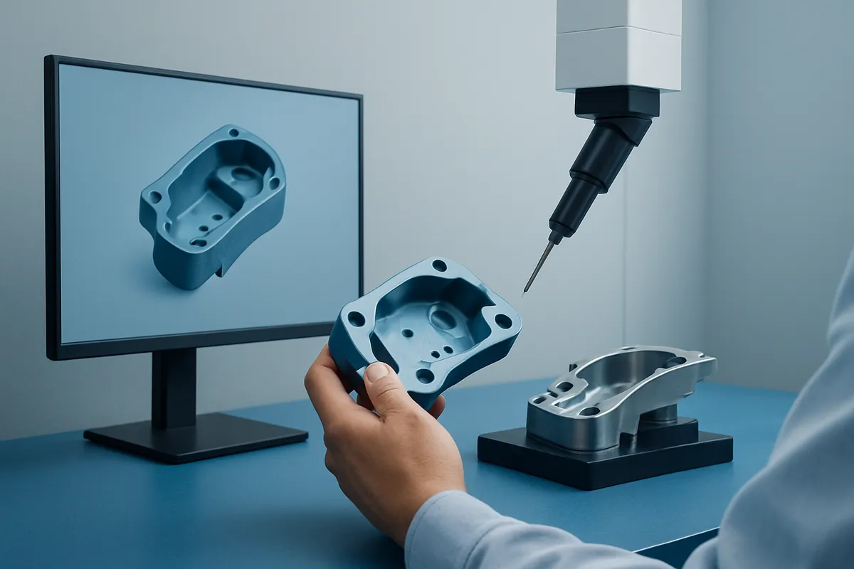
Verification in reverse engineering precision manufacturing typically involves re-scanning the finished machined part and overlaying it against the reconstructed CAD model using deviation analysis software. Color-map reports highlight regions where the machined surface falls outside the specified tolerance band. Critical functional surfaces — mating faces, bearing bores, fixation points — are prioritized in this review. A part passes verification only when every functional surface falls within the agreed tolerance, confirming the reverse engineering workflow produced a manufacturable, conforming result.
Conclusion
Reverse engineering earns its place in precision manufacturing when documentation is missing, a design needs improvement, or a supplier relationship has ended and production must continue. The process only delivers value when the measurement chain — scanner, software, CAD reconstruction — is accurate enough to feed the machining tolerances the finished part demands. For components held to ±0.001mm, that chain cannot have weak links.
If you have a physical part that needs to re-enter production, start by identifying whether you need external geometry only or internal features as well — that single decision determines whether optical scanning or CT scanning is the right first step. From there, request a quote from GC INDUS with the physical sample and any surviving drawings, however incomplete, to get an accurate assessment of what the reverse engineering and machining scope actually involves.
Recommended Articles
Explore more from our content library:


