
Book Appointment Now

GC INDUS / MANUFACTURING KNOWLEDGE
How to Achieve Tight Tolerances on Thin-Walled Parts

Understanding how to achieve tight tolerances manufacturing is essential. Achieving tight tolerances (±0.001mm) on thin-walled parts requires four things working together: rigid workholding that prevents part flex, machines with proven thermal stability and low spindle runout, CAM programming that accounts for tool deflection and heat buildup, and in-process measurement that catches drift before it produces scrap. Thin walls fail tolerance checks most often from clamping-induced distortion and cutting-heat expansion, not from machine inaccuracy alone, so the fix starts with how the part is held and cut, not just which machine holds the spec sheet’s rated accuracy.

What You’ll Need to Achieve Tight Tolerances in Manufacturing
Before cutting a single part, you need four things in place: a temperature-controlled floor, low-runout spindles, on-site metrology, and workholding built for thin walls. Skip any one of these, and how to achieve tight tolerances manufacturing at the ±0.001mm level becomes guesswork rather than a repeatable process.
Start with the shop environment. A floor that swings more than a couple degrees across a shift will expand and contract both the workpiece and the machine structure enough to push a ±0.0005″ spec out of range. Pair that with spindles rated for low runout, and back it with a calibrated CMM or optical comparator on the floor, not in a lab three buildings over, so you catch drift during the run, not after the batch ships.
How Material Properties Affect Your Ability to Hold Tight Tolerances
Material behavior under the tool determines how much of your tolerance budget goes to holding the part versus fighting it. Pre-hardened tool steels and select aluminum grades machine predictably because they resist the heat-driven distortion and work-hardening that plague gummy or highly reactive alloys. Modus Advanced’s engineering guidance notes that material selection affects achievability directly, some metals naturally support tighter tolerances, while others demand slower feeds, lighter cuts, and more frequent tool changes just to stay in spec. At GC INDUS, we select and machine aluminum, magnesium, iron, steel, and stainless steel based on how each responds to precision cutting, not just what the drawing calls out.
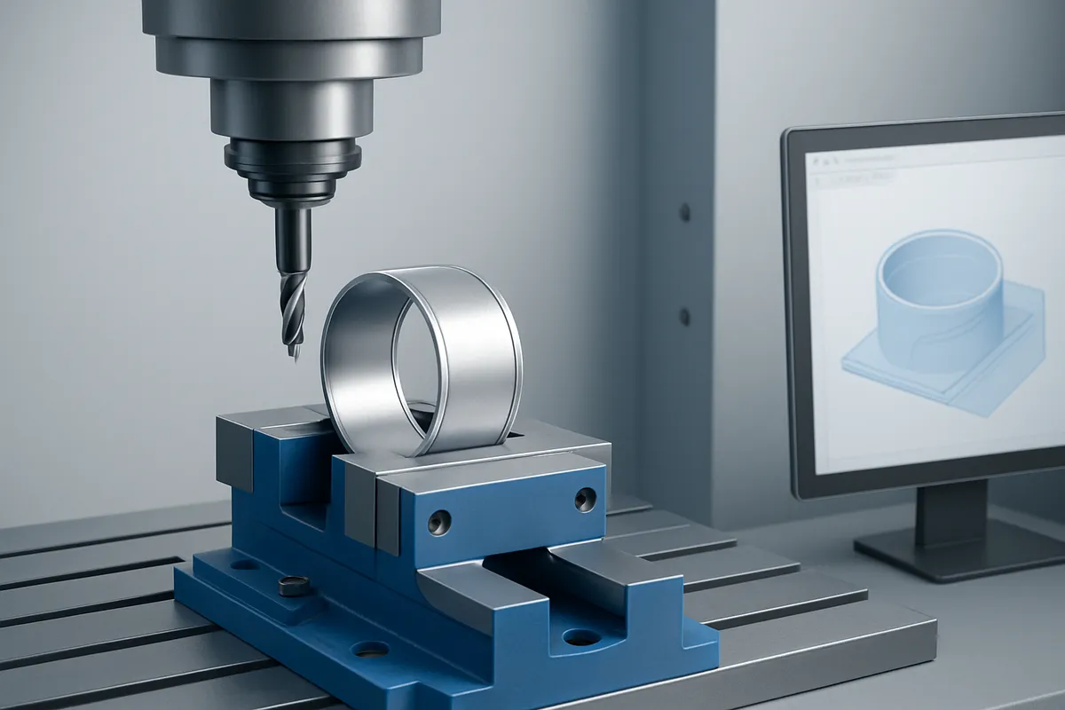
Thin walls raise the stakes further, since clamping force that a solid block shrugs off will bow, oval, or spring a thin section the moment pressure releases. Vacuum fixtures, custom soft jaws, or potting compounds that support the wall from the inside spread clamping load evenly and prevent the distortion that ruins an otherwise perfect cut.
On the programming side, your CAM software needs tool deflection compensation and adaptive toolpath features that adjust feed and depth in real time as cutting forces build. Finally, train operators to run in-process inspection during the cut cycle, not just at final QC, catching a 0.0003mm drift mid-run is the difference between a saved part and a scrapped one.
Configure Your CNC Process to Hold Tight Tolerances on Thin-Walled Parts
Holding ±0.001mm on a thin wall comes down to three linked decisions: how the CAM program sequences cuts, how the machine holds datums between operations, and how much heat and force the setup lets build up. Get any one wrong and the part moves after it leaves the fixture.
What CAM Strategies, Feeds, and Speeds Work Best for Tight Tolerance Programming
Thin sections flex under cutting force before they break tolerance, so the CAM strategy has to manage deflection, not just remove material efficiently. Staged roughing-to-finishing, cutting in progressively lighter passes rather than one aggressive pass, consistently beats simply slowing the whole job down.
- Rough in balanced, symmetric passes on opposite sides of a thin wall so heat and residual stress don’t build up on one face and pull the part out of round once it’s unclamped.
- Finish with light, consistent depth-of-cut passes, thin walls have almost no rigidity left by the finishing stage, so a single heavy pass can spring the wall and leave it out of tolerance even though the toolpath was correct.
- Use climb milling where the setup allows it; cutting in the direction that pushes the tool away from the workpiece reduces the deflection that pulls thin material into the cutter.
- Lower feed rates and shallower depth of cut on the last several passes, both reduce cutting force and heat, which are the two variables that most directly cause thin-wall distortion.
This sequencing logic is central to how to achieve tight tolerances manufacturing on parts that have little mass to resist cutting forces, the program has to compensate for what the geometry can’t.
5-Axis vs 3-Axis CNC Machines: Which Should You Invest In
A 5-axis machine earns its cost by cutting multiple faces in one setup, which eliminates the datum shifts that cause the most tolerance drift on complex thin-wall parts. Every time a part is unclamped and re-fixtured on a 3-axis machine, it reintroduces clamping variation, often the single largest source of out-of-round or out-of-flat results on thin material.
For simpler thin-wall geometry with two or three accessible faces, a well-programmed 3-axis setup with careful fixturing holds tight tolerances just as reliably, at lower capital cost. The deciding factor isn’t the number of axes on the spec sheet, it’s how many times the part needs to be repositioned to complete all its features. Fewer repositions mean fewer chances to lose the datum.
How Horizontal Mills Compare to Vertical Machining Centers for Tight Tolerance Work
Horizontal mills shed chips and dissipate heat more effectively during long production runs, which matters for thin walls because heat is a direct driver of dimensional drift. Vertical machining centers (VMCs) remain the more common choice for smaller thin-wall parts that need frequent tool changes and shorter cycle times, since they’re faster to set up and program for varied, lower-volume work.
A shop running high volumes of a single thin-wall geometry gets a real return from horizontal mill capacity. A shop handling varied prototype-to-low-volume orders, the profile most OEM and medical device buyers actually have, is usually better served by VMCs with strong fixturing and 5-axis access reserved for the genuinely complex jobs. GC INDUS runs both configurations across its CNC milling, turning, and 5-axis lines specifically because no single machine type fits every thin-wall job, and matching the machine to the part’s complexity and volume is what keeps ±0.001mm tolerances repeatable across a full production run rather than just achievable on a first-article sample.
Prevent Thermal Drift, Tool Wear, and Spindle Runout From Ruining Your Tolerances
Three mechanical failure modes cause most out-of-spec parts: thermal drift, tool wear, and spindle runout, each needs a distinct process control, not a general fix. Understanding how to achieve tight tolerances manufacturing at ±0.001mm means treating these as separate variables you monitor independently, not as one vague “machine calibration” problem.
Thermal drift happens because spindle motors, servo drives, and cutting friction generate heat that expands the machine’s structure and the workpiece itself. A part measured perfectly at 8 a.m. can drift out of tolerance by mid-afternoon as the spindle housing grows a few microns. We control this with thermal soak time, running the machine through a warm-up cycle before cutting production parts, and by stabilizing coolant temperature so it doesn’t swing with ambient shop conditions.
Tool wear is quieter and more dangerous because the edge degrades gradually, changing cutting forces and surface finish well before it looks visibly dull. A worn edge pushes harder against thin walls, deflecting the part and altering the final dimension even though the toolpath hasn’t changed. Tracking tool life by cycle count rather than by eye catches this before it shows up in scrap, a tool swapped at 8,000 cycles based on data outperforms one swapped “when it looks worn.”
Spindle runout, wobble caused by bearing wear or an imbalanced toolholder, throws the cutting edge off-center, which directly enlarges bore diameters and degrades roundness. Scheduled runout checks with a dial indicator or laser measurement system catch this drift before it reaches the part, since runout tends to worsen slowly across thousands of spindle hours rather than failing all at once.
A Step-by-Step Troubleshooting Process When Parts Start Missing Tolerance
When a batch starts drifting, isolate the failure mode systematically instead of guessing.
- Compare first-part and last-part measurements from the run. A gradual dimensional shift across the batch points to thermal drift or tool wear; a sudden jump points to a mechanical event like a bearing failure or a workholding shift.
- Check tool hours against the tracked cycle count. If the tool is near or past its rated life, replace it and re-run a sample part before continuing production.
- Pull the ambient temperature log for the shop floor and the coolant system. A swing of several degrees during the shift often correlates with the exact window parts started drifting.
- Take a spindle runout reading with a dial indicator or laser system. Anything above the machine’s rated tolerance for that operation confirms bearing wear or toolholder imbalance as the root cause.
This sequence usually narrows the failure to one variable within a single shift, which is faster and cheaper than halting the line to recalibrate everything. GC INDUS builds this kind of tracking into its inspection protocols across CNC milling, turning, and 5-axis work, so drift gets caught at the process level before it reaches final inspection.
Verify and Measure Tight Tolerances Before Parts Leave the Floor
Confirming ±0.001mm tolerances takes a mix of contact and non-contact measurement plus trend tracking across the run, not just a single go/no-go check at the end. Any answer to how to achieve tight tolerances manufacturing has to include verification, because a part that measures in spec at first article can still drift out of spec by piece 200 if nobody is watching the process in between.
CMM vs Optical Inspection vs SPC for Validating Tight Tolerances
A coordinate measuring machine (CMM) is the right tool when a part has complex geometric features, true position, profile of a surface, multiple datums referenced in GD&T callouts. A CMM probe touches the part at defined points and builds a 3D map accurate to sub-micron levels, but each cycle takes minutes, not seconds, which makes it a poor fit for validating every unit in a high-volume run.
Optical or vision inspection solves a different problem: speed and part fragility. A camera-based system measures edges, diameters, and hole locations without touching the surface, which matters directly for thin-walled components that can flex or mark under the contact pressure of a CMM probe. Thin walls distort easily during clamping and cutting, and that same sensitivity to force applies at the inspection stage, a probe pressing on a 0.3mm wall can deflect it enough to produce a false reading.
Statistical process control (SPC) takes a third approach. Instead of inspecting one part in isolation, SPC plots dimensional data across the run, control charts flag a trend moving toward the tolerance limit before any single part actually fails. This catches tool wear, thermal drift, or spindle degradation while there’s still time to adjust, rather than discovering a problem after fifty scrapped parts.
The practical answer is to combine all three based on part fragility and batch size: SPC for continuous, real-time monitoring during production, then CMM or optical inspection for final validation depending on geometry and wall thickness. A rigid, geometrically complex part gets CMM confirmation; a delicate thin-wall sleeve gets optical measurement.
None of this holds up in an audit without records. Every inspection result needs to trace back to a specific machine, tool, and operator, so a customer, or an ISO 9001 auditor, can reconstruct exactly how a given part was produced and verified. GC INDUS ties inspection data to that level of traceability as part of its standard quality protocol across CNC, casting, and molding jobs.
Common Mistakes to Avoid When Pursuing Tight Tolerance Manufacturing
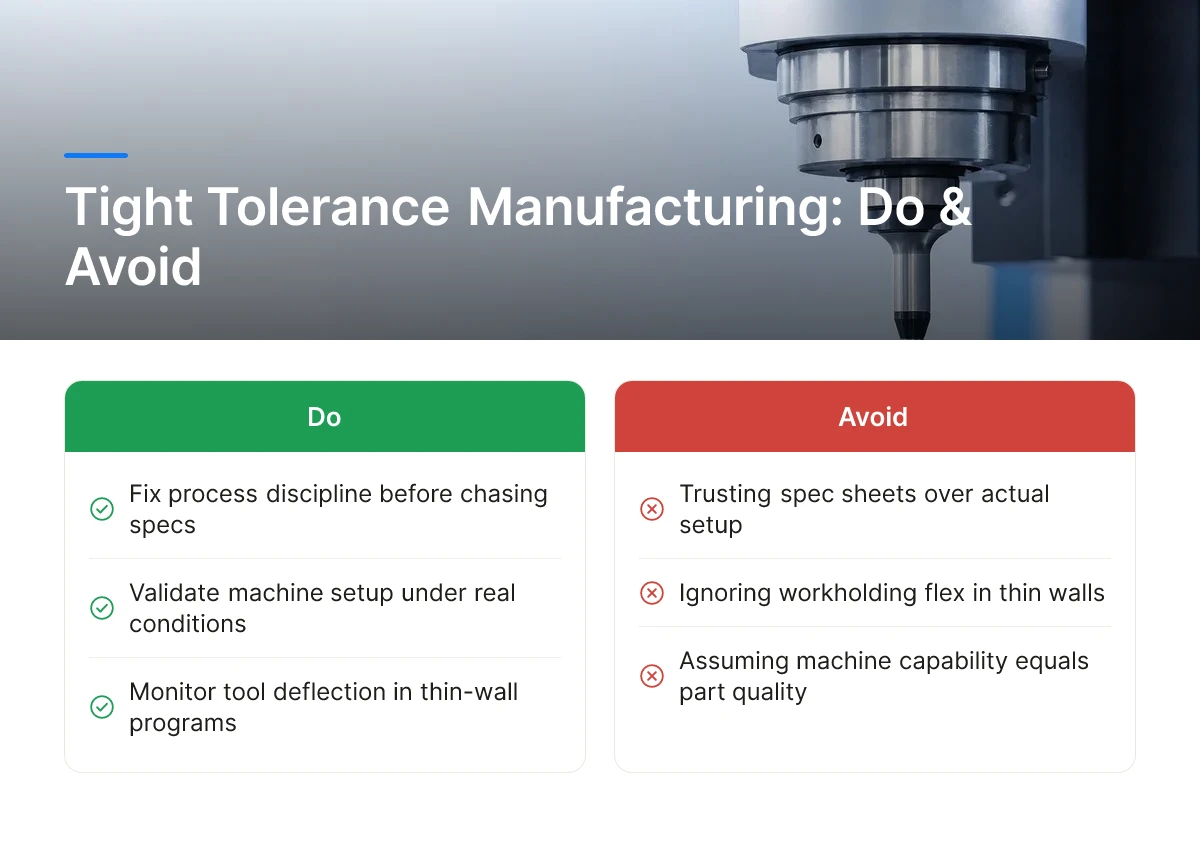
Most shops that miss tight tolerance targets on thin-walled parts already own the equipment to hit them, the failure sits in process discipline, not machine capability. Understanding how to achieve tight tolerances manufacturing at scale means fixing these recurring errors before they show up in a customer’s inspection report.
Trusting the Spec Sheet Over the Setup
A machine rated for ±0.001mm repeatability can still turn out scrap if the workholding flexes or the program ignores tool deflection. Spec sheets describe what the machine can do under ideal conditions, they say nothing about how a thin wall behaves once clamping force, cutting force, and heat act on it together. Programming has to account for staged roughing and finishing passes, not just the machine’s rated accuracy.
Skipping Thermal Soak to Save Cycle Time
Cutting thermal soak time is one of the most common ways shops trade a few minutes of cycle time for hours of rework. Temperature swings of just a few degrees, combined with tool runout, can push an entire batch out of spec at tolerances near ±0.0005 in. First-part and last-part drift is usually a thermal signature, not a random defect, the fix is controlling the environment before the cut, not adjusting the program after.
Inspecting Only the Last Part Off the Line
Checking one part at the end of a run tells you nothing about how the process behaved for the other 99. Gradual tool wear shows up as a trend, not a single failure, so shops that skip in-process trend monitoring miss the drift until an entire batch is already out of tolerance.
Under-Investing in Workholding
Thin-wall fixturing is where budgets get cut and quality gets lost. The fixture, not the machine, is often the true limiting factor on a thin-walled part, since uneven clamping pressure is the leading cause of out-of-round and waisted-OD failures.
Weighing the Investment
Frame the decision around scrap reduction, rework avoidance, and audit-readiness rather than a single return figure. Better fixturing, thermal control, and trend-based inspection mean fewer rejected parts, fewer customer returns, and faster PPAP approval, the real payoff. GC INDUS builds these controls into every run, backed by ISO 9001 and ISO 13485 quality systems, so tolerance holds from the first piece to the last.
Frequently Asked Questions
Can every material hold a ±0.001mm tolerance, or are some materials unsuitable?
No, material behavior sets a practical floor on achievable tolerance. Stainless steel and tool steel hold tight dimensions well because of high stiffness and low thermal expansion, while soft aluminum alloys and most plastics distort more under cutting force and heat. Material selection should happen alongside tolerance specification, not after the design is locked.
Do thin-walled parts always need 5-axis machining to hit tight tolerances?
Not always, 5-axis machining helps but process route and fixturing usually matter more for thin walls. Staged roughing-to-finishing passes, proper support, and controlled cutting parameters address deflection and vibration directly. A 3-axis setup with the right workholding can outperform a poorly programmed 5-axis job.
How often should spindle runout be checked during a tight-tolerance production run?
Check spindle runout at the start of every shift and after any tool change on tight-tolerance jobs. At tolerances near ±0.0005 inch, a tenth of a thousandth of runout can push a batch out of spec, so frequent verification catches drift before it scraps parts.
Is optical inspection reliable enough to replace CMM for tight tolerance parts?
Optical inspection works well for surface features and quick checks, but CMM remains the standard for verifying dimensional tolerances at the ±0.001mm level. Quality assurance programs for tight-tolerance production typically pair both methods rather than relying on one exclusively.

Conclusion
Holding ±0.001mm on thin-walled parts comes down to controlling variables before they compound: match material to tolerance early, stage roughing and finishing to manage deflection, and verify spindle and thermal conditions throughout the run rather than only at final inspection. Skipping any one of these invites scrap, not just rework.
GC INDUS builds these controls into every job, backed by ISO 9001 and ISO 13485 quality systems and full inspection protocols from prototype through production. If you have a thin-walled part currently running out of spec, send the print and current inspection data for a fast quote and a review of where the process is losing tolerance.
Recommended Articles
Explore more from our content library:


