
Book Appointment Now

GC INDUS / MANUFACTURING KNOWLEDGE
How to Specify CNC Machining Tolerances for Precision Mechanical Parts
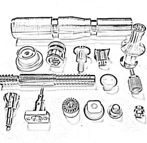

When ordering custom CNC machined parts, dimensional accuracy is one of the first subjects engineers and procurement teams need to address.
A drawing may contain dozens or even hundreds of dimensions, but not every dimension needs to be manufactured to the same tolerance.
This is an important distinction.
If tolerances are unnecessarily tight, machining time, inspection requirements, tooling costs, and rejection risk can all increase. On the other hand, tolerances that are too loose may prevent the finished component from assembling or functioning correctly.
The objective is therefore not simply to achieve the smallest possible tolerance.
The objective is to specify the right tolerance for the function of the part.
For manufacturers of machinery, automation equipment, fluid systems, industrial components, and other precision products, understanding how CNC machining tolerances work can make a significant difference in part quality and total manufacturing cost.
GC INDUS provides precision machining services for custom metal and plastic components, supporting CNC milling, CNC turning, Swiss machining, multi-axis machining, finishing, and inspection requirements.
This guide explains how to specify CNC machining tolerances, which dimensions typically require tighter control, how tolerances affect manufacturing cost, and what engineering teams should communicate when requesting a quotation.
1. What Is a CNC Machining Tolerance?
A machining tolerance defines the acceptable variation from a nominal dimension.
For example, if a drawing specifies:
20.00 ± 0.05 mm
the acceptable dimensional range is:
19.95–20.05 mm
The nominal dimension is 20.00 mm, while the total tolerance zone is 0.10 mm.
A tolerance does not mean the manufacturer should randomly produce a dimension anywhere within that range.
A capable manufacturing process should be centered around the target dimension while maintaining the required process capability.
The appropriate tolerance depends on:
- Part geometry
- Material
- Machining process
- Machine capability
- Tooling
- Workholding
- Temperature
- Inspection method
- Production volume
- Functional requirements
Therefore, tolerance should always be considered together with the manufacturing process.
2. Why Tolerance Matters
Tolerances directly influence whether components fit and function correctly.
Consider a simple shaft and bearing assembly.
If the shaft diameter is too large, assembly may become impossible.
If it is too small, excessive clearance may cause vibration, movement, or premature wear.
The same principle applies to:
- Bearing seats
- Mating holes
- Bushings
- Pins
- Gear interfaces
- Sealing surfaces
- Locating features
- Threaded components
- Assembly interfaces
For these features, dimensional variation can directly affect product performance.
However, a decorative outer surface may not require the same precision.
This is why engineers should distinguish between functional dimensions and non-functional dimensions.
3. Not Every Dimension Needs Tight Tolerance
One of the most common mistakes in mechanical drawings is applying unnecessarily tight tolerances to every dimension.
For example, a drawing might specify ±0.01 mm across many dimensions even though only two or three features actually require that level of accuracy.
This can create unnecessary manufacturing costs.
Tighter tolerances may require:
- More precise tooling
- Additional machining operations
- Slower cutting conditions
- Additional setups
- Grinding
- Temperature control
- More frequent tool compensation
- More detailed inspection
Instead of tightening every dimension, identify the dimensions that affect:
Fit + Function + Alignment + Performance
Those dimensions should receive the appropriate tolerance.
4. General Tolerances vs Individual Tolerances
Engineering drawings commonly use general tolerances for dimensions that do not have individual tolerance specifications.
For example, a drawing may specify an ISO general tolerance standard.
This allows designers to avoid specifying a tolerance next to every single dimension.
However, critical features should still receive specific requirements.
A shaft bearing seat might require a tighter tolerance than the overall shaft length.
A mounting hole might require positional control while the surrounding plate dimensions can use a general tolerance.
This approach makes drawings easier to understand and helps manufacturers identify what is actually important.
GC INDUS provides ISO tolerance information for engineers working with dimensional requirements.
5. Dimensional Tolerance
Dimensional tolerance controls the size of a feature.
Typical examples include:
- Length
- Width
- Height
- Diameter
- Hole size
- Slot width
- Wall thickness
For CNC turning, diameter tolerance is particularly important.
For CNC milling, dimensions such as pocket width, hole diameter, and feature location can be critical.
The required tolerance should be based on the mating relationship.
For example:
A loose structural bracket may tolerate a relatively broad dimensional range.
A precision locating pin may require substantially tighter dimensional control.
6. Hole and Shaft Fits
Hole-and-shaft relationships are among the most common applications of tolerance engineering.
Depending on the application, an assembly may require:
- Clearance fit
- Transition fit
- Interference fit
A clearance fit allows relative movement or easy assembly.
An interference fit creates a tight mechanical connection.
A transition fit falls between these two conditions.
Engineers should specify the intended fit rather than simply choosing an extremely small tolerance.
This allows the manufacturer to understand the functional objective.
7. Positional Tolerance
A hole can have the correct diameter but still be in the wrong location.
This is where positional tolerance becomes important.
For example, imagine a mounting plate with four bolt holes.
Each hole may have a diameter of exactly 10 mm.
However, if one hole is several tenths of a millimeter away from its intended position, the component may not assemble correctly.
Therefore, engineers may need to control:
- Hole location
- Pattern position
- Center distance
- True position
- Datum relationships
This is one reason GD&T can be valuable for precision mechanical drawings.
8. Flatness, Parallelism and Perpendicularity
Dimensional tolerance alone does not describe every geometric requirement.
A surface can have the correct overall thickness but still be warped.
A hole can have the correct diameter but not be perpendicular to the surface.
Two surfaces can have the correct dimensions but fail to remain parallel.
Geometric controls such as:
- Flatness
- Parallelism
- Perpendicularity
- Straightness
- Circularity
- Cylindricity
- Position
- Runout
may therefore be required.
The correct geometric control depends on the functional relationship between features.
9. Runout and Concentricity in Rotating Parts
Rotating components can require special attention to alignment.
Examples include:
- Shafts
- Spindles
- Rollers
- Bushings
- Rotating housings
- Coupling components
A shaft can meet its diameter specification while still having excessive runout.
Excessive runout can contribute to:
- Vibration
- Uneven wear
- Poor sealing
- Noise
- Reduced bearing life
For rotating components, engineers should identify the relevant datum and specify the appropriate geometric requirement.
CNC turning is commonly used for these components, and GC INDUS provides CNC turning for custom cylindrical parts.
10. Surface Finish Is Different From Dimensional Tolerance
Surface roughness and dimensional tolerance are related to manufacturing quality, but they are not the same requirement.
For example:
Ø20.00 ±0.02 mm
controls the size of a cylindrical feature.
A requirement such as:
Ra 0.8 μm
controls surface roughness.
A part can have the correct diameter but an unsuitable surface finish.
Conversely, a very smooth surface does not automatically mean the dimension is correct.
Therefore, drawings should specify surface finish separately where it affects performance.
Depending on the application, GC INDUS can coordinate surface treatment and finishing requirements.
11. Material Influences Achievable Tolerance
Different materials behave differently during machining.
Aluminum is relatively easy to machine but can be sensitive to deformation in thin sections.
Stainless steel can work-harden and generate significant cutting forces.
Titanium can generate heat and require carefully controlled cutting conditions.
Engineering plastics can experience thermal expansion and deformation.
Therefore, the same nominal tolerance may have different manufacturing implications depending on the material.
This is particularly important when specifying thin-wall or large components.
GC INDUS supports multiple material options for custom components.
12. Part Size Also Matters
A tolerance that is practical for a small component may become more challenging for a large component.
For example, maintaining a tight tolerance across a small 30 mm component may be easier than maintaining the same dimensional relationship across a large 500 mm component.
Larger parts can be affected by:
- Thermal expansion
- Machine travel
- Workholding
- Material stress
- Tool deflection
- Setup variation
- Measurement uncertainty
Therefore, tolerance requirements should always be evaluated relative to part size and geometry.
13. Thin Walls and Deformation
Thin-wall components can be particularly challenging.
During machining, cutting forces may cause the material to deflect.
After material is removed, internal stresses can also cause dimensional changes.
This can occur with:
- Aluminum housings
- Stainless steel covers
- Thin brackets
- Aerospace structures
- Lightweight machine components
Designers should therefore avoid unnecessary thin walls when possible.
When thin sections are functionally necessary, the manufacturing process should account for:
- Workholding
- Roughing sequence
- Finishing allowance
- Toolpath strategy
- Stress relief
- Final inspection
14. Deep Cavities and Tool Deflection
Deep pockets and narrow cavities can also affect dimensional accuracy.
As tool length increases, tool deflection and vibration can become more significant.
Potential results include:
- Oversized or undersized features
- Poor surface finish
- Tapered walls
- Chatter
- Reduced tool life
For complex parts, 5-axis CNC machining can sometimes improve tool access and reduce the number of setups.
However, 5-axis machining is not automatically required.
The correct manufacturing process should be selected according to part geometry.
15. Tolerance and CNC Turning
Turning is particularly effective for cylindrical components.
Typical controlled dimensions include:
- Outside diameter
- Inside diameter
- Bore
- Groove width
- Thread diameter
- Shoulder location
- Overall length
For a precision shaft, several dimensions may interact.
For example, the relationship between:
Shaft diameter + shoulder position + runout + surface finish
may determine whether a bearing or coupling performs correctly.
This is why precision turning requires more than simply achieving the nominal diameter.
16. Tolerance and Swiss Machining
Swiss-type machining is commonly used for small, high-precision components.
Typical applications include:
- Pins
- Bushings
- Small shafts
- Connectors
- Medical components
- Precision fittings
Because the workpiece is supported close to the cutting area, Swiss machining can be advantageous for small and slender parts.
GC INDUS provides Swiss lathe machining for precision small-diameter components.
17. Tolerance Stack-Up
A single component may meet every individual tolerance and still create an assembly problem.
This can happen because of tolerance stack-up.
Consider an assembly containing:
- Housing dimension
- Shaft dimension
- Bearing thickness
- Spacer thickness
- Washer thickness
Each component has its own variation.
When these variations combine, the total assembly variation may become significant.
Engineers should therefore perform tolerance stack-up analysis when assembly performance depends on multiple dimensions.
The goal is not to make every part extremely precise.
The goal is to control the dimensions that have the greatest effect on assembly performance.
18. How Tolerance Affects CNC Machining Cost
Tolerance is one of the factors that can significantly influence machining cost.
A general component may require standard CNC machining and routine inspection.
A high-precision component may require:
- Multiple finishing passes
- Specialized tooling
- Additional setups
- In-process measurement
- CMM inspection
- Grinding
- Environmental control
The difference can be substantial.
This is why procurement teams should avoid requesting “maximum precision” without defining what precision is actually required.
A better RFQ identifies the critical features and their functional requirements.
19. Inspection Methods for Tight Tolerances
Inspection should match the tolerance and feature.
Common inspection tools include:
- Calipers
- Micrometers
- Height gauges
- Bore gauges
- Pin gauges
- Thread gauges
- Optical measurement
- CMM
For complex three-dimensional geometry, CMM inspection may be appropriate.
For simple diameter requirements, a micrometer may provide an efficient measurement method.
The inspection method should provide sufficient accuracy relative to the tolerance being verified.
20. First Article Inspection
For new components, first article inspection can help verify that the manufacturing process meets the drawing requirements.
A first article inspection may include:
- Dimensional results
- Material information
- Surface finish
- Heat-treatment records
- Special-process documentation
This can be particularly useful for:
- New product introduction
- Aerospace components
- Automotive components
- Medical products
- Complex machinery
- Repeat production programs
If FAI is required, it should be specified before production begins.
21. How to Write Tolerance Requirements on a Drawing
A clear drawing should distinguish between:
Critical Dimensions
Features that directly affect function or assembly.
Standard Dimensions
Dimensions that can use the applicable general tolerance.
Reference Dimensions
Dimensions provided for information rather than manufacturing control.
Geometric Requirements
Requirements such as position, flatness, parallelism, perpendicularity, and runout.
Surface Requirements
Ra values or other surface-finish specifications.
This structure makes the drawing easier for both the supplier and inspection team to interpret.
22. Design for Manufacturability
Good tolerance specification begins during product design.
Before releasing a drawing, ask:
- Does this dimension affect function?
- Does it affect assembly?
- Does it control a critical interface?
- Does it need a geometric tolerance?
- Can a standard tolerance be used?
- Can the tolerance be relaxed without affecting performance?
These questions can identify unnecessary manufacturing constraints.
A DFM review can also reveal opportunities to simplify:
- Tool access
- Internal radii
- Setup requirements
- Workholding
- Machining sequence
- Inspection
23. Tolerance and Production Volume
Production volume also influences how tolerance should be achieved.
For prototypes, CNC machining provides flexibility.
For low-volume production, optimized CNC processes can provide repeatability without expensive dedicated tooling.
For high-volume production, additional processes such as cold forging, precision casting, molding, or automated machining may become attractive.
GC INDUS provides multiple manufacturing solutions so the production method can be evaluated according to geometry, quantity, tolerance, and cost objectives.
24. Common Tolerance Specification Mistakes
Several mistakes appear frequently in machining RFQs.
Mistake 1: Making Every Dimension Tight
This increases cost without necessarily improving function.
Mistake 2: Ignoring Geometric Tolerances
Dimensional accuracy alone may not guarantee correct assembly.
Mistake 3: Not Defining Datums
Without clear datums, different parties may interpret feature relationships differently.
Mistake 4: Mixing Units
Using both metric and imperial dimensions without clear control can create errors.
Mistake 5: Ignoring Surface Finish
A dimension may be correct while the surface remains unsuitable for the application.
Mistake 6: Adding Requirements After Quotation
Inspection and certification requirements should be communicated before production.
Mistake 7: Choosing Tolerances Without Considering Process Capability
A tolerance should be realistic for the selected manufacturing process.
25. What Procurement Teams Should Include in an RFQ
A strong CNC machining RFQ should include:
1. CAD model
Preferably a current revision.
2. 2D engineering drawing
With dimensions, tolerances, GD&T, material, finish, and notes.
3. Quantity
Prototype, sample, batch, or annual volume.
4. Material
Including grade and condition where applicable.
5. Surface treatment
Such as anodizing, passivation, plating, polishing, or coating.
6. Inspection requirements
FAI, dimensional report, CMM, material certificate, CoC, etc.
7. Delivery requirements
Target lead time and destination.
Providing this information early helps the manufacturer evaluate the project more accurately.
26. Frequently Asked Questions
1. What tolerance can CNC machining achieve?
The achievable tolerance depends on material, geometry, machine, tooling, process, and inspection method. A supplier should evaluate the specific component rather than assuming one tolerance applies to every CNC process.
2. Should every CNC dimension have a tight tolerance?
No. Tight tolerances should generally be reserved for dimensions that affect function, fit, alignment, or performance.
3. What is the difference between dimensional tolerance and GD&T?
Dimensional tolerance controls feature size, while GD&T provides a system for controlling geometric relationships such as position, flatness, orientation, and runout.
4. Does tighter tolerance always mean better quality?
No. A tighter tolerance is only better when the application requires it. Unnecessary precision can increase cost without improving performance.
5. Does material affect CNC tolerance?
Yes. Material properties such as hardness, thermal expansion, residual stress, and machinability can influence dimensional stability.
6. Can CNC turning achieve tighter tolerances than milling?
Neither process is universally more accurate. The achievable result depends on the specific geometry, machine, tooling, workholding, material, and process strategy.
7. When should I use CMM inspection?
CMM inspection can be useful for complex parts or components with multiple dimensional and geometric requirements. The appropriate inspection method should match the required tolerance.
8. How can I reduce CNC machining costs without sacrificing quality?
Identify truly critical dimensions, use appropriate general tolerances elsewhere, simplify geometry where possible, reduce unnecessary setups, and clearly define functional requirements.
Conclusion
CNC machining tolerance should be treated as a functional engineering requirement rather than simply a specification for maximum precision.
The most effective drawings distinguish between:
Critical dimensions + General dimensions + Geometric requirements + Surface requirements
The right tolerance depends on the part’s:
- Function
- Material
- Geometry
- Size
- Manufacturing process
- Assembly requirements
- Inspection method
- Production volume
By controlling only the features that genuinely require precision, engineering teams can achieve reliable performance while avoiding unnecessary manufacturing costs.
GC INDUS supports precision CNC machining for custom mechanical components and can review drawings, material requirements, tolerances, finishing specifications, inspection requirements, and production quantities as part of the quotation process.
If you have a CNC component with demanding tolerance requirements, send the drawing and CAD model to the engineering team for review.


