
Book Appointment Now

GC INDUS / MANUFACTURING KNOWLEDGE
How Fixture Design Manufacturing Delivers Tight Tolerances

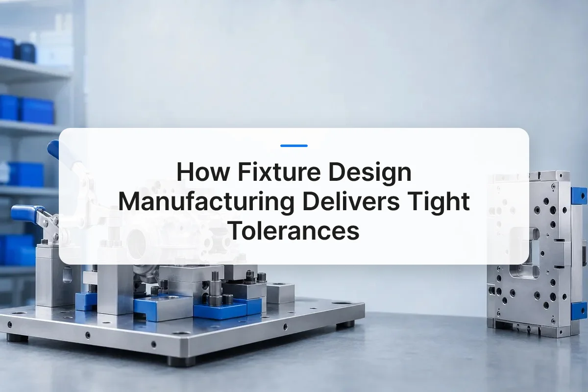
Fixture design manufacturing is the process of engineering workholding devices that locate and clamp a part in a fixed, repeatable position so every machining, inspection, or assembly operation hits the same tolerance, often ±0.001mm, across hundreds or thousands of cycles. Good fixture design controls three things: part location (locating datum surfaces), part restraint (clamping without distortion), and repeatability (swapping parts in and out without losing accuracy). Without it, even a highly accurate CNC machine will produce inconsistent parts because the part itself isn’t held the same way twice.
What Is Fixture Design and Why Does It Matter for Precision Manufacturing?
Fixture design manufacturing exists to solve one problem: a machine can only cut as accurately as the part is held. A CNC machine rated to ±0.001mm repeatability means nothing if the part shifts, tilts, or flexes between operations.
What Does Fixture Design Mean for Repeatable, High-Precision Manufacturing?
A fixture holds and locates a workpiece in a fixed position while a cutting tool operates on it, it does not guide the tool itself. That distinction matters. A jig guides the cutter directly, often through bushings, so the tool follows a path set by the jig. A fixture instead references the machine’s own axes and simply keeps the part still and correctly positioned, operation after operation. For a broader overview of how fixtures fit into modern production systems, see this explainer on fixtures in modern manufacturing.
General workholding, a vise, a chuck, a set of clamps, holds a part, but it doesn’t guarantee the part lands in the same location every time. Fixture design manufacturing is the engineering discipline that turns generic clamping into repeatable, datum-referenced positioning. It defines which surfaces locate the part, how many contact points establish that location, and how clamping force gets applied without disturbing it.
Machine accuracy and part accuracy are two different things. A five-axis machine can hold its own positioning to a fraction of a micron, but if the part sits at a slightly different angle or height each cycle, that machine precision never reaches the finished part. The fixture is what carries machine accuracy into part accuracy.
What Are the Main Goals of Fixture Design at Tight Tolerances?
At ±0.001mm, fixture design has to hit three goals at once: consistent location cycle after cycle, minimal deflection under clamping force, and fast load/unload times that don’t erode cycle efficiency. Miss any one, and the tolerance budget disappears before the cutting tool even engages.
Every source of fixture error stacks directly into the final part. Locating error from worn or poorly placed datum surfaces, clamping distortion from uneven or excessive force, and gradual wear on locators all add up, and that stack-up often consumes more of the tolerance band than the machining process itself.
Custom parts and prototypes raise the stakes further. A production run with years of fixture history has already found and fixed its weak points. A one-off or short-run part has none of that, the fixture has to get location and clamping right the first time, and because volumes are low, fixture cost per part is much harder to absorb. This is where fixture design manufacturing becomes a cost and quality decision as much as an engineering one, particularly for medical and aerospace components where a single out-of-tolerance part can mean a scrapped batch.
What Are the Core Principles of Fixture Design for Holding Tight Tolerances?
Tight-tolerance fixture design manufacturing rests on three engineering rules: fix each part’s position with the minimum contact points needed, clamp toward the locators instead of away from them, and keep the fixture stiff and thermally stable across the entire run. Break any one of these and tolerance drift shows up somewhere between part 1 and part 500, not necessarily on the first piece off the fixture.
What Is the 3-2-1 Principle in Fixture Design?
The 3-2-1 principle uses six contact points to remove six degrees of freedom, three translations and three rotations, so a rigid part has exactly one possible position in the fixture.
Three points sit on the primary plane and stop the part from rocking, tipping, or rotating around two axes at once. Two points on a secondary plane, usually perpendicular to the first, stop rotation around the remaining axis and lateral shift. One point on a tertiary plane blocks the last translational degree of freedom. Each point removes exactly one degree of freedom, no more. Add a seventh contact and the part is over-constrained, which we cover below.
Three points on the primary plane matter because a plane only needs three points to be fully defined, a fourth point on an imperfect real-world surface either does nothing or forces the part to bend to reach it, both of which reintroduce the rocking the fixture was supposed to eliminate. A short video walkthrough of these locating principles is available here.
What Key Elements and Components Go Into a Well-Designed Fixture?
Locating pins, V-blocks, nests, and datum surfaces each answer a different geometry problem, and picking the wrong one is a common source of repeatability loss in fixture design manufacturing.
- Locating pins, used for holes and bosses; a diamond pin paired with a round pin controls rotation without binding when hole spacing varies slightly part to part.
- V-blocks, self-centering for cylindrical stock, holding round parts on their true center regardless of diameter variation within tolerance.
- Nests and datum surfaces, machined to match a part’s profile or reference plane, used when the part geometry itself needs to define the locating scheme rather than isolated points.
Clamping force placement matters as much as locator choice. Clamps must push the part into the locators, not away from them, a clamp positioned opposite a locating pin, for instance, seats the part harder against the datum, while a clamp angled off-axis can lift or skew the part off its reference points entirely, producing parts that measure fine on the fixture but fail on the CMM.
Fixture stiffness and thermal stability decide whether that repeatability holds for part 1 and part 10,000. A fixture that flexes under clamping load or expands unevenly as coolant and cutting heat build up over a shift will drift out of tolerance gradually, not obviously, which is why dimensional checks across a run, not just first-article inspection, catch the failure mode over-constraining creates: redundant locators fighting each other, seating the part slightly differently every cycle.
What Types of Fixtures Are Used in Custom Manufacturing, and How Do You Choose the Right One?
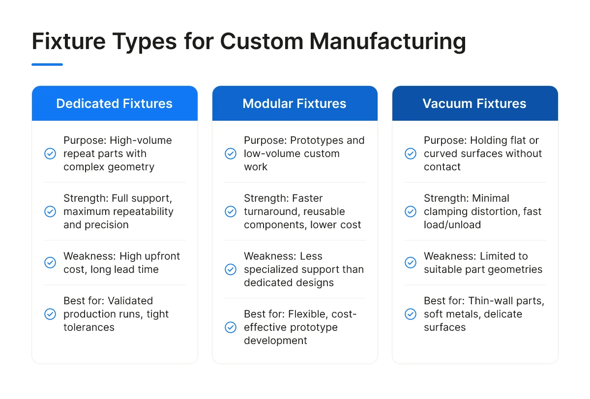
The right fixture type depends on production volume, part geometry, and tolerance, dedicated fixtures suit high-volume repeat parts, modular systems suit prototypes and low-volume runs.
What Are the Different Types of Fixtures and What Are Their Trade-offs?
Dedicated (hard) fixtures are built for one part number. They deliver the tightest repeatability because every locator and clamp is machined to that part’s geometry, but tooling lead time can run from days to weeks, and the cost isn’t recoverable if the design changes.
Modular fixtures use standardized plates, risers, clamps, and locating pins that get reconfigured for different jobs. They cost less upfront and can be assembled in hours rather than weeks, which makes them the default choice during early-stage fixture design manufacturing for prototypes or parts still under revision.
Vacuum fixtures hold thin, flat, or delicate parts, sheet metal panels, thin-wall plastics, composite skins, without mechanical clamping marks. They’re fast to set up but limited to parts with enough surface area to seal against, and they lose holding force if the part has holes or an irregular profile.
Pallet systems don’t hold the part directly; they carry fixtures (or parts) between machining stations or through multi-axis operations without re-referencing the origin point. They add throughput on production runs but represent unnecessary overhead for a one-off prototype. For a deeper look at how these trade-offs play out in practice, see this guide on streamlining manufacturing through fixture design.
- Dedicated fixtures: best for high-volume, stable designs; highest upfront cost, longest lead time, best repeatability.
- Modular fixtures: best for prototypes and low-volume custom parts; lowest upfront cost, fastest turnaround, reusable across projects.
- Vacuum fixtures: best for thin, flat, or soft-surfaced parts; fast setup, geometry-limited.
- Pallet systems: best for multi-station production; adds automation value only at volume.
A dedicated fixture earns its cost when a part has complex geometry that needs full support on every surface, or when the run size is large enough that the per-part savings in cycle time and scrap offset the tooling investment. Below that threshold, modular fixturing wins on flexibility alone, a customer iterating through three prototype revisions in a month doesn’t want a new hard fixture each time.
How Do Material Choices Affect Fixture Performance and Lifespan?
Fixture body material determines how well a setup holds tolerance over thousands of cycles, and the trade-off is between wear resistance, weight, and thermal stability.
Tool steel resists wear and holds locating features accurately over long production runs, which suits dedicated fixtures for automotive or industrial parts run in the tens of thousands. It’s heavy and costs more to machine, which is wasted expense on a fixture that will only see a handful of prototype parts.
Aluminum machines faster, weighs less, and works well for modular fixture plates and low-to-mid-volume work, though it wears faster under repeated clamping and has a higher coefficient of thermal expansion, a factor that matters when a fixture design manufacturing process holds tolerances near ±0.001mm and shop temperature isn’t tightly controlled.
Composite or polymer fixture bodies show up in vacuum fixtures and lightweight modular components where wear is minimal but handling weight matters, such as fixtures moved by hand between stations.
Part geometry and material drive these choices as much as volume does. A thin-wall aluminum housing needs distributed support across its surface to avoid distortion under clamping force, favoring vacuum or multi-point modular locating rather than a few hard clamps. A cast part with an as-cast surface and dimensional variation from the mold needs locators that reference machined datums rather than the rough surface, while a fully machined blank can locate directly off finished features. Soft metals like magnesium mark easily, which pushes fixture design toward broader contact pads and lower clamping pressure than steel or titanium parts would need.
How Do You Design Fixtures for Cost-Effective Manufacturing Without Sacrificing Precision?
Cost-effective fixture design manufacturing matches tooling investment to run length and tolerance, spending on dedicated hardware only where volume justifies it.
Every fixture cost gets amortized over the number of parts it produces. A dedicated fixture machined from hardened tool steel makes sense for a high-volume automotive production run, where the per-part tooling cost shrinks to a small fraction of the total. That same fixture applied to a small prototype order carries an unreasonable burden per part, since the entire tooling investment has to be recovered across a tiny batch. For low-volume or one-off custom parts, modular fixturing, reusable base plates, interchangeable locators, adjustable clamps, spreads tooling cost across many different jobs instead of one.
How Do Optimized Fixtures Compare to Standard Approaches on Cost and Precision?
An optimized fixture matches precision and hardware to the part’s actual tolerance band, while a standard or over-engineered fixture adds cost without adding accuracy. Specifying a ground-and-hardened locating pin for a feature toleranced at ±0.05mm doesn’t improve the outcome, it just adds machining time, heat treatment cycles, and lead time that the part didn’t ask for. Excess precision in a fixture is a cost with no corresponding return; it doesn’t make the workpiece more accurate once the fixture’s repeatability already exceeds what the part drawing requires.
Design-for-manufacturability thinking helps keep fixture cost down without cutting corners on repeatability. Standardizing locating features, common datum holes, consistent clamping points, across a part family lets one fixture base serve several variants with swappable inserts instead of a fully custom build for each. Off-the-shelf tooling components, such as catalog clamps, locating pins, and modular grid plates, cost less and lead time faster than custom-machined equivalents, and they’re often precise enough for mid-tolerance work.
Cutting fixture cost too aggressively backfires if it introduces scrap or rework. A loose-fitting locator or an under-clamped part shifts during machining, and out-of-tolerance parts erase whatever was saved on the fixture itself, sometimes several times over, once material, machine time, and inspection labor are counted. The decision is a tier choice: budget-friendly modular setups suit prototypes and short runs, while premium dedicated fixtures earn their cost once a design is validated and production volume is confirmed. GC INDUS sizes fixture investment to each project’s run length and tolerance band, so prototype work isn’t paying for production-grade tooling it doesn’t need.
What Tools and Emerging Technologies Are Changing Fixture Design Manufacturing?
Simulation software, 3D-printed components, and sensor-equipped platforms now let engineers test and validate fixture behavior digitally before any metal is cut. These technologies are pulling fixture design manufacturing away from trial-and-error prototyping and toward predictive, data-backed builds.
What CAD Platforms and Fixture Design Software Are Widely Used?
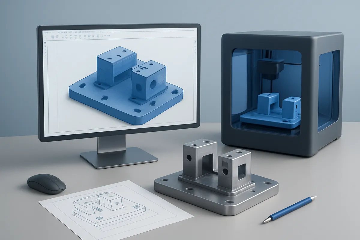
CAD/CAM platforms with built-in simulation modules let designers model clamping force, contact pressure, and part deflection before a single fixture plate is machined. An engineer can load a part’s CAD model, apply expected cutting loads, and see where a thin-walled aluminum housing might flex under clamp pressure, then adjust locator placement or clamp geometry in the software rather than on the shop floor.
This matters for tolerance-critical work. If a fixture over-clamps a part and induces even a few microns of distortion, the finished component can drift outside spec once released from the fixture. Simulation-driven design catches this class of error early, cutting down on the number of physical fixture iterations needed to hit tolerance and shortening prototype cycles that once required multiple rounds of cut-fit-adjust.
How Are Additive Manufacturing and Industry 4.0 Reshaping Fixture Design?
3D printing has changed the economics of low-volume and custom fixture design manufacturing. Soft jaws, locators, and nests that once required a toolmaker to machine from stock can now be printed directly from CAD data, cutting lead time for one-off or short-run fixtures from days to hours in many shops. This is especially useful for prototype runs or engineering changes, where a fixture might only see a handful of parts before the design shifts again.
Industry 4.0 principles are also reaching the fixture itself. Sensor-equipped fixtures can measure clamping force, confirm part presence, or flag misalignment in real time, feeding that data directly into quality systems for traceability, a capability that matters for regulated industries like medical devices, where every part needs a documented chain of custody. The broader trend is modular, sensor-ready fixture platforms that swap components quickly between part families while staying connected to production data systems.
At GC INDUS, fixture and tooling decisions are validated against these same principles, simulation for tolerance-critical geometry, modular tooling for flexible production, before parts move into CNC machining, die casting, or injection molding, with full inspection protocols confirming the fixture held its intended tolerance through the run.
Frequently Asked Questions
What’s the difference between a fixture and a jig?
A fixture holds and locates a workpiece but doesn’t guide the cutting tool; a jig does both. Fixtures are common in milling, inspection, and welding, where the machine or operator controls tool path. Jigs are typically used for drilling or boring, where bushings physically guide the drill bit to the correct position on the part.
How often should fixtures be inspected or recalibrated to maintain tolerance?
Inspect production fixtures on a fixed schedule tied to cycle count, not calendar time—every 5,000 to 10,000 cycles is a common starting point. High-wear locators and clamps need more frequent checks. Tight-tolerance work (±0.001mm) warrants shorter intervals and a logged calibration record for audit purposes.
Can one fixture be used across multiple part variants?
Yes, with modular or adjustable locators designed for a defined family of parts sharing common datum features. Quick-change baseplates, interchangeable locating pins, and adjustable clamps let one fixture body serve several variants. This works best when part geometry differs in size or minor features, not in datum scheme.
What causes a fixture to lose repeatability over time?
Wear on locating pins and clamp contact points is the most common cause, followed by loosened fasteners and buildup of chips or debris on locating surfaces. Thermal expansion during long production runs and accidental impact damage also shift reference points. Regular cleaning, torque checks, and wear-part replacement prevent most drift.
Who should be involved in fixture design manufacturing decisions on a new project?
Fixture design manufacturing works best as a shared decision between the part design engineer, the machinist running the operation, and quality staff who own the inspection plan. Involving all three early catches conflicts between locating scheme and part function before tooling is cut, and it keeps the fixture aligned with how the part will actually be measured and accepted.
Conclusion
Fixture design decides whether ±0.001mm tolerances hold on part one or drift by part one thousand. Get the datum scheme, clamping force, and material selection right up front, and inspection becomes a formality rather than a fire drill. Skip that rigor, and no amount of machine precision will save the run.
If you’re specifying a new fixture for a production part, start by mapping your critical-to-function features to a 3-2-1 datum scheme before you touch a CAD model for the fixture body itself. GC INDUS engineers fixtures alongside part programs under ISO 9001 and ISO 13485 protocols, so tolerance intent carries through from prototype to full production run.
Recommended Articles
Explore more from our content library:


