
Book Appointment Now

GC INDUS / MANUFACTURING KNOWLEDGE
Understanding Porosity in Die Casting and Its Impact on
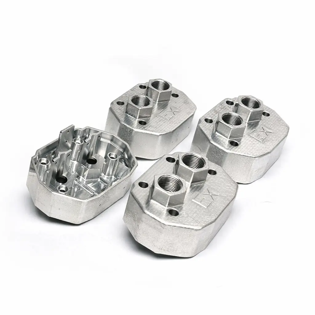
Understanding porosity die casting reliability is essential. Porosity in die casting, trapped gas pockets or shrinkage voids inside a casting, directly threatens part reliability by reducing tensile strength, fatigue life, and pressure-tightness. Even small voids can cause structural failures under cyclic load or leak paths in hydraulic components. Controlling porosity through process design, mold engineering, and rigorous inspection is the primary lever for achieving consistent, field-reliable die cast parts.

What Is Porosity in Die Casting and Why Does It Threaten Reliability?: porosity die casting reliability
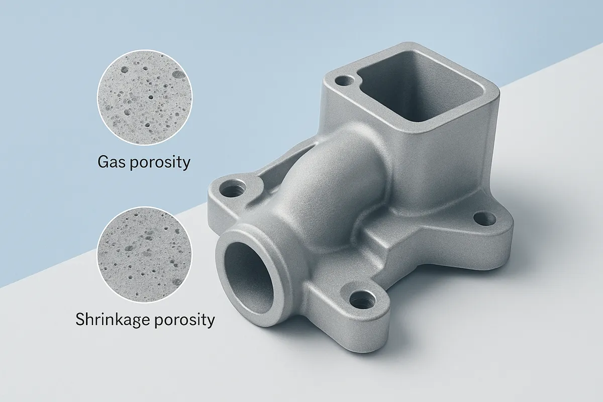
Porosity in die casting describes internal voids, either gas-entrapment bubbles or solidification-shrinkage cavities, that reduce a part’s load-bearing cross-section and compromise structural integrity.
Gas porosity forms when air or steam becomes trapped as molten metal fills the die at high speed. Shrinkage porosity forms during solidification, when metal contracts and insufficient liquid metal feeds the cavity. Both defect types occupy volume that should be solid material, and both directly affect porosity die casting reliability in ways that matter from the design phase onward.
How Porosity Affects Mechanical Properties and Part Performance
A void inside a casting acts as a stress concentrator. Under cyclic or impact loading, cracks initiate at void edges and propagate through the surrounding material, reducing tensile strength, elongation, and fatigue life well below what the base alloy specification predicts.
Pressure-tightness is a separate but equally critical concern. Even sub-millimeter interconnected pores create continuous leak paths through a wall. Hydraulic manifolds, fuel system housings, and medical device enclosures cannot tolerate this, a single leak path under operating pressure constitutes a functional failure, not a cosmetic one.
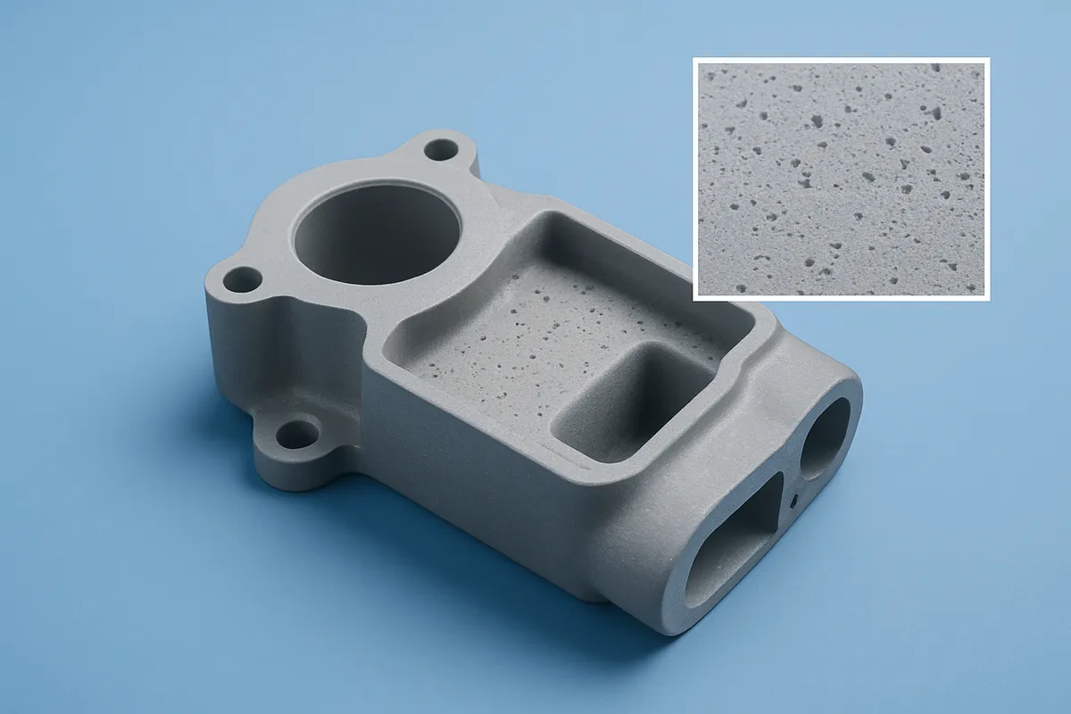
Surface porosity is visible and catchable during visual inspection. Subsurface porosity is the more dangerous failure mode: it goes undetected without X-ray, CT scanning, or pressure testing, and it can pass final inspection only to fail in the field.
Real-World Cost Impacts of Porosity Failures in Automotive, Aerospace, and Medical Applications
Automotive structural brackets, aerospace housings, and medical implant components each carry zero tolerance for unexpected porosity-driven failures. A recalled automotive transmission housing or a leaking surgical instrument enclosure generates warranty costs, regulatory exposure, and reputational damage that far exceeds the cost of upstream process control.
This is why porosity is a design-phase concern, not a QC afterthought. By the time a porous part reaches final inspection, or worse, the field, the cost of failure has already compounded through machining, finishing, and assembly labor applied to a defective casting.
What Causes Gas Porosity and Shrinkage Porosity in Aluminum Die Castings?
Both defect types trace to distinct physics: gas porosity comes from dissolved hydrogen precipitating during rapid solidification; shrinkage porosity comes from aluminum’s ~6–7% volumetric contraction outpacing metal feed.
Gas Porosity: Hydrogen Dissolution and Entrapment
Molten aluminum readily absorbs hydrogen from moisture in the die cavity, release gases in lubricants, and ambient atmosphere. As the metal solidifies under high injection pressure, solubility drops sharply and the dissolved gas precipitates into bubbles. Those bubbles freeze in place before they can escape, leaving spherical voids distributed through the casting.
The faster the fill, the more turbulence, and turbulence folds air into the melt before the die cavity is fully purged. This is the central gas-entrapment mechanism in standard high-pressure die casting.
Shrinkage Porosity: Volumetric Contraction and Inadequate Feeding
Aluminum contracts roughly 6–7% by volume as it transitions from liquid to solid. When molten metal cannot feed into late-solidifying regions fast enough, isolated voids form, typically irregular in shape and concentrated at thick-to-thin wall transitions where the thermal gradient is steepest.
Alloy composition amplifies this risk. Alloys with a wide freezing range, meaning a large temperature gap between liquidus and solidus, remain semi-solid for longer, giving shrinkage more time to develop. Near-eutectic compositions solidify more abruptly and are generally less prone to shrinkage porosity.
The Role of Cooling Rates, Wall Thickness, and Material Selection in Porosity Formation
Thick sections cool more slowly than thin ones, extending the solidification window and creating isolated hot spots where shrinkage voids concentrate. Abrupt thickness changes are particularly problematic: the thin wall freezes first and cuts off the feed path to the still-liquid thick region.
Uniform wall thickness and gradual transitions are the primary design-level controls. On the process side, die temperature management and targeted cooling channels directly affect local cooling rates, and therefore where shrinkage porosity forms. For more information, see Thegoodcode.
How Defect Rates Differ Between High-Pressure, Squeeze, and Vacuum-Assisted Die Casting
Each casting method carries a different porosity die casting reliability profile that engineers must weigh against part geometry and production volume.
- High-pressure die casting (HPDC): Fastest cycle times and lowest per-part cost, but turbulent fill creates the highest gas entrapment risk of the three methods.
- Squeeze casting: Applies sustained mechanical pressure throughout solidification, suppressing both gas bubble formation and shrinkage voids, producing near-wrought material density in critical sections.
- Vacuum-assisted die casting: Evacuates the die cavity before injection, removing the air that would otherwise be entrapped. This cuts gas porosity significantly without the tooling complexity of squeeze casting.
No single method eliminates all porosity. The right choice depends on the part’s wall geometry, the required internal integrity, and whether post-cast machining will expose subsurface voids.
How Mold Design and Process Control Reduce Porosity Risk
Gate placement, vent sizing, and parameter tuning are the primary engineering controls that determine porosity die casting reliability before a single shot is fired.
Gate, Runner, and Venting Design
Gate location dictates how the metal fill front moves through the cavity. Position gates so molten metal advances progressively from one end to the other, pushing displaced air toward vents rather than folding back on itself and trapping gas mid-cavity. A fold-back fill pattern, sometimes called a “race-track” effect, is one of the most common causes of gas porosity in complex housings and brackets.
Venting works alongside gate design. Vent channels must have sufficient cross-sectional area to evacuate air fast enough to match injection speed; under-vented dies are a leading cause of gas porosity. Overflow wells placed at the last-to-fill zones capture the leading edge of the shot, which carries the highest gas concentration, and remove it from the functional cavity entirely.
Mold-fill and solidification simulation identifies high-porosity-risk zones before the tool is cut. Running flow analysis on a digital model lets engineers reposition gates or redesign cooling channels at the CAD stage, where changes cost a fraction of what they cost after steel is machined.
Design Trade-Offs to Minimize Porosity While Maintaining Reliability
Uniform wall thickness is the single most effective geometric control for shrinkage porosity, it allows the cavity to solidify at a consistent rate without isolated hot spots that pull metal inward. In practice, structural or packaging requirements often prevent perfectly uniform walls.
Adding ribs instead of increasing wall thickness is the preferred DFM approach when extra stiffness is needed. Ribs maintain wall uniformity, reduce part mass, and shorten cycle time, a genuine win on all three counts.
Optimizing Temperature, Pressure, and Injection Speed to Prevent Porosity
Injection speed, metal temperature, and die temperature must be tuned as a system, not independently. Too-high injection speed increases turbulence, which folds gas into the melt before it can escape through vents. Too-low metal or die temperature causes the leading edge to solidify prematurely, leaving shrinkage voids in areas the remaining melt can no longer feed.
GC INDUS controls these parameters through documented process sheets tied to each die and alloy combination, a practice that supports the repeatability required under ISO 9001 and, for medical-grade components, ISO 13485. Parameter drift between shifts is one of the underreported causes of batch-to-batch porosity variation, and locking parameters to a validated baseline is the most direct way to prevent it.
The Most Accurate Methods to Detect and Measure Porosity in Castings
X-ray CT scanning, 2D radiography, ultrasonic testing, and pressure testing each serve distinct roles in confirming porosity die casting reliability before parts reach the field.
No single method covers every scenario. Choosing the right technique depends on part geometry, void size, production volume, and the functional consequences of a missed defect. The sections below break down each method’s capability and appropriate use case.
X-Ray CT, Ultrasonic Testing, and Pressure Testing: Accuracy and Use-Case Comparison
X-ray CT scanning is the gold standard for subsurface porosity characterization. It produces a full 3D volumetric map of void size, location, and distribution without destroying the part, and can detect pores below 0.1 mm in favorable scan conditions. Aerospace and medical applications typically require CT because it provides complete internal characterization, though scan throughput is lower than other methods, making it better suited to sampling and critical-part verification than high-volume line inspection.
2D X-ray radiography is faster and less expensive than CT, making it practical for production-line sampling. It detects porosity along the beam path but cannot precisely locate void depth or characterize 3D geometry, a limitation that matters when specifying acceptable defect zones in a complex casting.
Ultrasonic testing (UT) works well for detecting larger voids and delaminations in thicker sections. It is less effective for small, dispersed gas porosity, and requires adequate probe access to the part surface. UT suits structural castings where wall geometry allows direct contact.
Pressure and leak testing validates functional pass/fail for hydraulic and pneumatic components directly. It confirms whether a part holds pressure under service conditions but cannot locate or size the voids responsible for a failure. Most production teams use it as a final gate before shipment, not as a primary characterization tool.
Machining as an unintended reveal step deserves attention. Stock removal exposes subsurface porosity at the cut surface, turning a hidden defect into a visible, and expensive, late-stage discovery. Inspecting castings before machining, using CT or radiography, avoids the cost of scrapping a fully machined part.
How Industry Standards and Design Trade-Offs Define Acceptable Porosity Levels
ASTM and ISO standards define porosity acceptance grades by application, giving engineers a contractual, measurable basis for porosity die casting reliability decisions.
What ASTM and ISO Specifications Say About Acceptable Porosity Limits
ASTM B85 covers aluminum alloy die castings and references radiographic inspection as a quality control method. Paired with ASTM E505—which provides reference radiographs for aluminum and magnesium die castings—buyers and suppliers use a five-grade severity scale (grade 1 being the least porous, grade 5 the most) as contractual acceptance criteria. That scale turns a subjective “minimize porosity” instruction into a documented, auditable standard.
ISO 10049 applies specifically to radiographic examination of aluminum castings and categorizes porosity by void size and distribution across the cross-section. Aerospace and pressure-containing components typically require the tightest grades under both standards. A hydraulic valve body or structural aerospace bracket may demand grade 1 or zero detectable porosity in critical zones, while a non-structural cosmetic bracket can accept grade 3–4 porosity with no functional consequence.
Using Reliability Calculations to Set Porosity Acceptance Criteria
Standards define the scale; reliability engineering defines where on that scale a specific part must land. Weibull fatigue analysis and fracture mechanics allow engineers to calculate the maximum allowable void diameter that keeps a part above its required safety factor at design load. That calculation converts a qualitative goal into a quantitative threshold—say, no void larger than 0.8 mm in a fatigue-critical bore—that the foundry can verify through X-ray or CT inspection.
The most practical application of this approach is zoning. Engineers specify critical and non-critical porosity regions directly on the part drawing, allowing the foundry to concentrate process controls—adjusted shot velocity, targeted venting, or vacuum assistance—where structural risk is highest. At GC INDUS, die cast parts are inspected against customer-specified acceptance criteria, with full inspection protocols that map findings to drawing-defined zones rather than applying a single blanket standard across the entire casting.
Frequently Asked Questions
Can porosity in die castings be repaired after the fact?
Yes, surface and near-surface porosity can often be repaired using impregnation, welding, or epoxy filling—but internal voids in structural or pressure-critical zones are rarely fixable without scrapping the part. Vacuum impregnation with anaerobic resin is the most common repair method; it seals interconnected pores and restores pressure integrity without altering dimensions. The practical limit is that impregnation works on fine, distributed porosity, not on large shrinkage cavities. Parts with voids in sealing faces or load-bearing walls typically require a process correction upstream, not a downstream fix.
Is porosity more common in aluminum die casting than in zinc or magnesium?
Aluminum die casting generally produces higher porosity rates than zinc, primarily because aluminum has a wider solidification range and lower fluidity, which promotes both gas entrapment and shrinkage voids. Zinc alloys solidify faster and fill cavities more completely, reducing gas porosity risk. Magnesium sits between the two—it flows well but is highly reactive with moisture in the die, which can generate hydrogen gas and create localized porosity if die lubrication and moisture control are not tightly managed.
How does vacuum-assisted die casting reduce porosity compared to standard high-pressure die casting?
Vacuum-assisted die casting evacuates air from the die cavity before and during injection, cutting the volume of trapped gas by up to 90% compared to standard high-pressure die casting. With less air present, the molten metal fills the cavity without compressing gas pockets into voids. The result is measurably lower gas porosity, better mechanical properties, and parts that can pass pressure testing at specifications that standard HPDC castings routinely fail. The trade-off is higher tooling complexity and cycle cost.
At what porosity level does a die casting typically fail pressure testing?
There is no single universal threshold—acceptable porosity limits depend on the application, alloy, and test pressure specified by the customer or standard. That said, interconnected porosity of any size in a sealing zone will cause a pressure test failure because gas or fluid finds a path through the part. For structural automotive and hydraulic components, many OEM specifications cap total porosity at 0.5–1% of cross-sectional area in critical zones, with zero tolerance for through-porosity regardless of overall percentage.
Conclusion
Porosity in die casting is manageable, not inevitable—but only when process control, tooling design, and inspection are treated as a system rather than separate checkboxes. Three actions matter most: specify porosity acceptance criteria on your drawing before tooling is cut, require X-ray or CT inspection data for any pressure-critical or structural application, and verify that your casting supplier controls shot velocity, die temperature, and venting as documented process parameters, not informal adjustments.
If your current supplier cannot provide process control records alongside dimensional reports, that gap is worth addressing before your next production run. GC INDUS holds ISO 9001 certification and runs full inspection protocols on die cast components—request a quote with your STEP file and porosity specification to get a concrete assessment of what your part requires.
Recommended Articles
Explore more from our content library:


