
Book Appointment Now

GC INDUS / MANUFACTURING KNOWLEDGE
How Shrinkage Allowance in Die Casting Affects Part Size
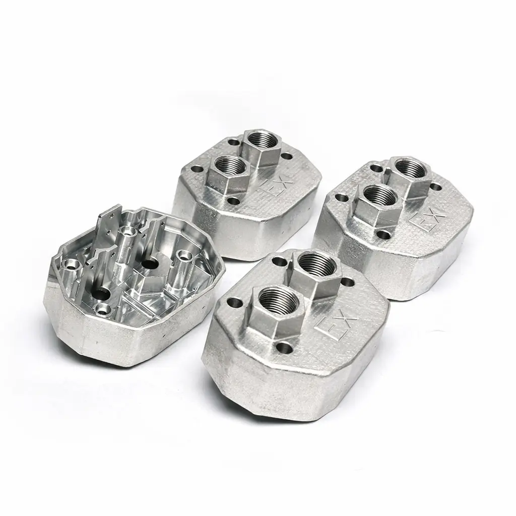
Understanding shrinkage allowance die casting is essential. Shrinkage allowance in die casting is the percentage added to a part’s design dimensions to compensate for the metal contracting as it cools and solidifies in the mold. Without it, finished parts come out undersized and fail tolerance checks. Allowance values vary by alloy, aluminum, zinc, and magnesium each shrink at different rates, and must be built into the tool design before machining the die, since correcting cavity dimensions after cutting is costly. Getting this right upfront is what lets die casters hold tight tolerances consistently.

What Is Shrinkage Allowance in Die Casting and Why Does It Matter for Tight Tolerances?
Shrinkage allowance in die casting is a dimensional correction factor built into cavity design so a cooling casting lands at its intended final size, not smaller. This is particularly relevant for shrinkage allowance die casting.
Metal doesn’t shrink in one step. It contracts in three distinct stages as it moves from molten to solid:
- Liquid shrinkage while the metal is still fluid in the shot sleeve and runner
- Solidification shrinkage as it transitions from liquid to solid
- Solid-state cooling shrinkage as the fully solid part continues to cool to room temperature
Because the die is a rigid steel cavity that constrains the part’s outer geometry during solidification, most of the volumetric change a die caster has to design around happens during that final solid-state cooling stage, after the part has already taken its shape but before it fully cools and pulls away from the die walls. Getting shrinkage allowance die casting calculations right at this stage is what separates a tool that produces in-spec parts from one that requires constant rework.
What Is the Typical Shrinkage Rate for Aluminum Die Castings Compared to Other Alloys?
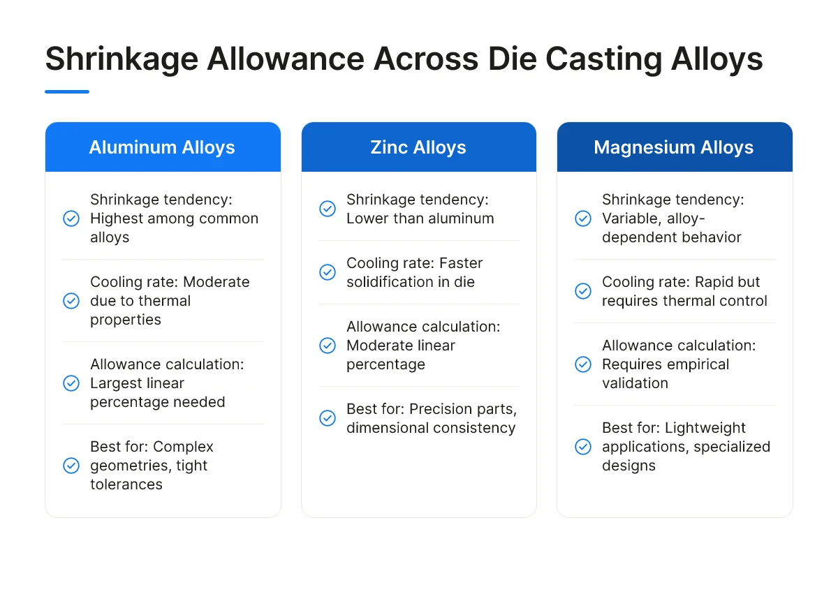
Aluminum alloys generally shrink more than zinc and land somewhere above magnesium’s range, which is why cavity allowances differ by alloy rather than using one universal value. This relative ordering, aluminum shrinking more aggressively than zinc, with magnesium falling in its own band based on alloy chemistry and wall thickness, is why toolmakers select allowance percentages per material rather than applying a flat rule across a shop’s whole part mix. Wall thickness, gate location, and cooling rate all shift the actual number within an alloy’s typical range, which is why allowance tables are a starting point, not a substitute for validation on the first shots. For more background on why metals contract unevenly during solidification, see this overview of shrinkage in metal casting and how to prevent it.
How Does Shrinkage Allowance Help Meet Tight Customer Tolerance Requirements?
An unaccounted shrinkage rate produces a casting that is uniformly undersized against the print, and undersized parts are far harder to rescue than oversized ones, there’s no material left to machine back to nominal. That mismatch shows up as rework, scrap, or a failed dimensional inspection when a customer measures incoming parts against a tolerance callout. For OEM and medical device parts specified to tight, micron-level bands, the allowance has to be calculated and cut into the cavity before the die is machined, since the shrinkage compensation is what makes the as-cast dimension land inside the tolerance window in the first place. GC INDUS builds this allowance into tool design up front across aluminum, magnesium, iron, steel, and stainless steel die casting programs, holding tolerances as tight as ±0.001mm on finished parts.
What Factors Influence Shrinkage in Die Casting, and How Do They Differ From Other Casting Methods?
Gate location, cooling rate, and cavity pressure drive shrinkage in die casting, and each behaves differently than in gravity-fed processes like sand or investment casting. Getting a shrinkage allowance die casting figure right means accounting for all three together, not treating them as independent variables.
How Do Gate Location, Cooling Rate, and Cavity Pressure Affect Shrinkage in Die Casting?
Gate location decides how molten metal fills the die and which regions solidify last. Metal near the gate cools first because it contacts the die wall longest under pressure, while sections farthest from the gate, or areas fed by converging flow fronts, solidify last and shrink more. These last-to-solidify zones are where porosity and sink marks concentrate, so gate placement is one of the first variables our tooling engineers review when we set a shrinkage allowance for die casting.
Cooling rate is the second driver. Die temperature and wall thickness together determine how fast the metal loses heat, and faster cooling produces a finer grain structure with less shrinkage than the coarser grains that form under slow cooling. A thick boss next to a thin rib cools unevenly, which is why wall transitions need their own allowance adjustments rather than one blanket figure across the part.
Cavity pressure sets die casting apart from every other process discussed here. In high-pressure die casting, molten metal is forced into the die at pressure and held under pressure as it solidifies, mechanically compacting the metal and closing off the microporosity that gravity casting cannot prevent.
What’s the Difference in Shrinkage Allowance Between Die Casting, Investment Casting, and Sand Casting?
Sand casting relies on a loose, compressible sand mold and gravity fill, which gives the metal room to shrink unevenly and allows gas and shrinkage porosity to form more freely. Investment casting uses a rigid ceramic shell, which constrains the part geometrically but still fills by gravity, so shrinkage porosity forms in isolated pockets that are harder to predict, as explained in this piece on why casting shrinkage happens and how to avoid it. When considering shrinkage allowance die casting, this point stands out.
Die casting’s rigid steel die combined with injection pressure gives the process the most repeatable shrinkage behavior of the three. That predictability is exactly why die casters can specify tighter, smaller allowances than sand or investment foundries typically hold. In short, the three processes rank differently for shrinkage predictability:
- Die casting: rigid steel die plus injection pressure, most repeatable shrinkage, smallest practical allowances
- Investment casting: rigid ceramic shell, gravity fill, isolated and harder-to-predict porosity pockets
- Sand casting: loose, compressible mold and gravity fill, least predictable shrinkage and highest porosity risk
How Do You Calculate the Right Shrinkage Allowance for Your Die Casting Design?
Shrinkage allowance die casting calculations start with a linear shrinkage percentage applied to each nominal dimension, then adjusted for the geometry of individual features.
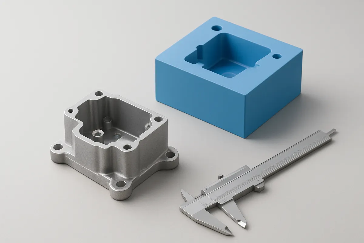
The base method is straightforward: multiply the target part dimension by the alloy’s expected linear shrinkage rate to get the corresponding cavity dimension in the die. That gives a starting allowance for the whole part. But no real part shrinks uniformly, a flat plate, a deep rib, and a thick boss on the same casting all cool at different rates, so the toolmaker adjusts the base allowance section by section rather than applying one flat number everywhere.
What Are the Specific Shrinkage Allowance Values for Common Die Casting Alloys?
Shrinkage tendencies vary by alloy family, and design teams treat these as starting ranges rather than fixed constants. Aluminum alloys generally shrink less than zinc during solidification and cooling, magnesium alloys tend to shrink at rates comparable to or slightly higher than aluminum, and zinc alloys, despite their lower melting point, often require careful allowance because of how they behave in thin-wall sections. Exact rates shift with specific alloy composition, gate design, and die temperature, which is why tool designers treat published shrinkage ranges as inputs to refine, not final answers. GC INDUS works across aluminum, magnesium, and zinc-family die casting alloys, and we set allowance ranges per alloy and part geometry before cutting steel, rather than applying a single generic factor across every job.
Can You Calculate Shrinkage Allowance Precisely, or Does It Require Empirical Testing?
Calculation gets you close, but empirical testing is still necessary because die deflection, thermal gradients, and alloy batch variation don’t behave predictably on paper. A calculated allowance assumes even cooling and consistent melt chemistry, real production rarely delivers either. Several part features commonly diverge from the calculated baseline:
- Wall thickness transitions that cause localized hot spots and shrink more than thin, fast-cooling sections
- Ribs and bosses, which hold more mass and pull material, shrinking at rates that diverge from the surrounding wall
- Die steel itself, which flexes slightly under injection pressure and repeated thermal cycling, shifting cavity dimensions in ways a shrinkage formula can’t capture in advance
This is why first-article inspection and trial shots remain standard practice even after careful calculation. A trial shot reveals where the calculated allowance held and where geometry or process conditions pushed a dimension out of tolerance, giving engineers real data to correct the tool before full production begins.
How Do You Apply Shrinkage Allowance in Your CAD Workflow and Part Design?
Applying shrinkage allowance in die casting means scaling the nominal CAD model by the alloy’s shrinkage factor, then re-checking every critical dimension against the customer drawing before cutting steel.
What’s the Practical Workflow for Building Shrinkage Allowance Into Your CAD Model Before Tooling?
We start with the nominal part geometry, the dimensions the customer actually wants on the finished component, taken straight from their drawing or STEP file. From there, we scale the entire model by the alloy’s shrinkage factor: roughly 0.5-0.6% for aluminum alloys and slightly higher for magnesium, depending on wall thickness and alloy grade. Once the model is scaled, we verify every critical dimension and datum against the original customer drawing to confirm nothing drifted out of tolerance during the transform. For those exploring shrinkage allowance die casting, this matters.
Most CAD packages handle this with a single uniform scale factor applied to the whole body, which works fine for parts with consistent wall thickness. It breaks down on parts with mixed sections, a housing with thick mounting bosses next to thin structural ribs won’t shrink at the same rate everywhere. Thicker sections cool slower and shrink more; thin sections lock in faster and shrink less. Those areas need manual adjustment on specific features rather than blanket scaling, which is why shrinkage allowance die casting work still depends on an engineer reviewing geometry section by section, not just running a script.
The scaled model becomes the master reference for cavity machining, the toolmaker cuts the die to these dimensions, not the nominal ones. This handoff has to happen before the die is cut. Catching a scaling error after steel has been machined means re-cutting the cavity, which costs time and tooling budget that a design review would have avoided.
Mating surfaces, bore diameters, and other tolerance-critical features get flagged for extra scrutiny at this stage, since small compounding errors there are the ones customers notice first. At GC INDUS, this verification step runs alongside our ISO 9001 quality checks before any tooling commitment, which helps hold finished parts to tolerances as tight as ±0.001mm once the die is cut and production starts.
What Do You Do When Parts Still Exceed Shrinkage Tolerances Despite Proper Allowance?
Out-of-spec parts after a correct shrinkage allowance calculation usually point to a process variable, not a bad formula, isolate the cause before touching the die.
How Do You Troubleshoot and Compensate When Die-Cast Parts Don’t Meet Dimensional Targets After Applying Standard Shrinkage Allowance?
Start by separating die design error from process drift. If every part from every shot runs oversized or undersized by roughly the same amount on the same feature, the cavity dimension itself is off, the shrinkage allowance die casting math built into the tool doesn’t match the alloy’s actual contraction. If instead the deviation varies shot to shot, or drifts over a production run, the cause is process-side: cooling time, injection pressure, or die temperature that’s crept away from its set point. Aluminum alloys are especially sensitive to die temperature swings, since a hotter die slows solidification and changes how much the casting pulls away from cavity walls.
First-article inspection and coordinate measuring machine (CMM) data catch this distinction early. Measuring the first parts off a new or reworked tool against the CAD model, before committing to a full run, flags an allowance mismatch while it’s still cheap to fix. Waiting until a batch is complete turns a tooling adjustment into a scrap problem.
Correct in order of cost. Recommended troubleshooting sequence:
- Adjust process parameters first: cooling time, gate velocity, injection pressure, and die temperature. These changes cost nothing beyond machine time and often resolve the deviation entirely.
- Re-inspect a fresh sample after each parameter change to confirm whether the deviation has closed.
- Only when parameter adjustments plateau, and the part still misses tolerance, consider cavity re-machining or an insert change, since that means recutting steel.
Document deviations by feature location, not just by part. A dimension that’s off only near a gate or in one wall section usually signals a local cooling or fill problem; a deviation spread evenly across the whole part points to a global shrinkage miscalculation in the original allowance.
Frequently Asked Questions
Does shrinkage allowance differ for thin-walled versus thick-walled die cast sections?
Yes, thinner walls cool faster and typically shrink less than thick sections, which retain heat longer and solidify more slowly. A part with mixed wall thickness needs zone-specific shrinkage values rather than one uniform allowance, especially where ribs, bosses, or gate areas sit next to thin walls. This directly impacts shrinkage allowance die casting outcomes.
Can shrinkage allowance eliminate the need for post-machining on critical dimensions?
No, shrinkage allowance narrows the gap to target dimensions but rarely replaces machining on features needing tolerances tighter than standard die casting can hold. Bearing bores, mating faces, and sealing surfaces still typically go through secondary machining, which is why GC INDUS pairs die casting with CNC finishing to hit tolerances as tight as ±0.001mm.
How does die temperature control affect shrinkage consistency across a production run?
Stable die temperature keeps cooling rates consistent, which keeps shrinkage consistent from shot to shot. If the die heats up over a long run or cools between cycles, shrinkage values drift, causing dimensional variation between early and late parts in the same batch. Consistent thermal control and in-process inspection catch this drift before it affects a full production lot.
Should shrinkage allowance be applied differently to functional features like bosses and ribs?
Yes, bosses and ribs are thicker relative to surrounding walls and cool more slowly, so they often need distinct shrinkage values from the main body. Applying one blanket allowance across the whole part risks warping, sink marks, or out-of-tolerance mounting holes on these features.
Do different shrinkage allowance standards apply across industries using die casting?
Shrinkage allowance itself is a physical property of the alloy and process rather than an industry-specific standard, but how tightly it must be controlled varies by application. Automotive and general hardware parts often tolerate the standard calculated allowance as-is, while medical and precision OEM components typically require tighter validation and secondary machining on critical features.
Conclusion
Shrinkage allowance is not a single number pulled from a materials chart, it is a calculation that shifts with alloy, wall thickness, gate location, and die temperature control. Treat it as a starting point validated by first-article inspection, not a fixed constant. Mixed-thickness parts need zone-specific values, and critical dimensions still benefit from secondary machining rather than relying on casting alone.
If your current supplier can’t show you their shrinkage calculation method or first-article inspection data, ask for it before your next tooling order. GC INDUS combines in-house die casting with CNC finishing and full inspection protocols to hold tight tolerances from the first shot onward, request a quote to review your part’s shrinkage plan before cutting steel.
Recommended Articles
Explore more from our content library:


