
Book Appointment Now

GC INDUS / MANUFACTURING KNOWLEDGE
Why Shrinkage Allowances in Die Casting Matter for Accuracy

Understanding shrinkage allowances die casting is essential. Shrinkage allowances in die casting are the compensation factors added to cavity dimensions in tooling design to offset the metal’s contraction as it cools from molten to solid state. Because each alloy shrinks at a different, fairly predictable rate, engineers scale up the die cavity dimensions during design so the final cast part lands within the customer’s required tolerance after cooling. Get the allowance wrong and the part comes out oversized or undersized, no amount of secondary machining can fix a systemic tooling error cheaply. Correct allowances are typically expressed as mm per meter of cast dimension and vary by alloy family, wall thickness, and process parameters.

What Are Shrinkage Allowances in Die Casting and Why Do They Matter for Tight Tolerances?: shrinkage allowances die casting
A shrinkage allowance is the percentage added to every cavity dimension during die design, calculated before a single cut is made in the tool steel.
Molten aluminum, zinc, or magnesium loses volume the moment it starts to solidify, and it keeps contracting, at a slower rate, as the solid casting cools from its freezing point down to room temperature. This is a two-stage process: liquid-to-solid shrinkage during the phase change, then solid-state thermal contraction afterward. Because the finished part will always end up smaller than the cavity that shaped it, tooling engineers cut the die cavity larger than the target part dimension, scaled by an allowance factor specific to the alloy being cast. For a broader look at why this contraction happens across metal casting processes generally, see this overview of casting shrinkage and why it happens.
What Happens When Shrinkage Allowances Are Miscalculated or Omitted
An incorrect shrinkage allowance doesn’t produce scattered, random errors, it produces a systemic bias across the entire production run. If the allowance is too small, every part trends undersized; too large, and every part trends oversized. This shows up clearly during first-article inspection, when the first parts off the tool are measured against the print and the deviation appears consistently across all critical dimensions rather than in isolated spots. That consistency is the signature of a shrinkage calculation error, distinct from the random variation you’d expect from process drift or material inconsistency.
Common signs that a shrinkage allowance was miscalculated or skipped entirely include:
- Every part from the run trending the same direction, oversized or undersized, rather than scattering around the target
- Deviation appearing across all critical dimensions at once instead of in one isolated feature
- First-article inspection results that don’t improve with process tweaks like pressure or temperature adjustments
- A pattern that repeats identically across shifts, operators, and machines, ruling out process drift as the cause
How Shrinkage Allowance Differs From Other Tolerance Compensation Methods
Shrinkage allowance is a tooling design input, decided and locked in before the die is cut. Machining allowance and secondary finishing, by contrast, are post-cast corrections applied to a part that already exists, adding stock for a finish pass, or grinding a mating surface to spec. Those methods fix localized surface conditions; they cannot correct a cavity that was cut to the wrong overall size. Confusing the two is a common design-stage mistake.
This is why shrinkage allowances die casting decisions belong at the front of the design process, not as a fallback. Once the die is cut, correcting a wrong allowance means re-machining the cavity, adding weld and re-cut steel, or scrapping the tool entirely, all costly, slow options compared to getting the calculation right the first time.
How Do Shrinkage Allowances Differ Across Aluminum, Magnesium, and Zinc Die Casting Alloys?
Shrinkage allowances die casting engineers apply are expressed as mm per meter of cast dimension, and the value swings meaningfully by alloy family. A tooling designer who copies an aluminum shrinkage factor onto a zinc or magnesium tool will cut a cavity that produces out-of-tolerance parts before the first shot cools. For more detail on the mechanics behind this variation, see this explanation of shrinkage in metal casting and how to prevent it.
Why Do Different Alloys Require Different Shrinkage Compensation Factors?
Aluminum alloys generally demand a higher shrinkage allowance than zinc alloys because of how each metal moves through its solidification range. Aluminum cools across a wider temperature spread before it fully solidifies, and that extended transition drives more volumetric contraction as the casting sets in the die.
Zinc behaves differently. Its shrinkage tends to run lower and more consistent from shot to shot, which is a large part of why zinc is the alloy of choice for small, tight-tolerance components, connector housings, precision gears, and hardware where a few hundredths of a millimeter matter. The narrower, more predictable contraction gives tooling designers a stable factor to cut against.
Magnesium sits apart from both. Its own coefficient of thermal expansion and distinct solidification behavior mean magnesium shrinkage cannot be estimated by adjusting an aluminum table. Designers need alloy-specific shrinkage data for magnesium rather than assuming a proportional relationship to aluminum or zinc figures.
The mechanical reason behind all three differences comes down to composition, the split between liquid-to-solid solidification shrinkage and continued solid-state cooling contraction after ejection, and the grain structure each alloy forms as it freezes. Alloys with coarser grain structures and wider freezing ranges contract more unevenly, which is why every alloy family needs its own allowance rather than a single universal number carried across a die casting program.
In short, the factors that drive different shrinkage allowances die casting engineers must account for by alloy include:
- Width of the solidification temperature range, wider ranges generally mean more contraction
- Grain structure formed as the alloy freezes, coarser grains shrink more unevenly
- Alloy composition and its specific coefficient of thermal expansion
- The split between liquid-to-solid shrinkage and continued solid-state cooling contraction after ejection
What Process Parameters Affect Shrinkage Calculations in Die Casting Design?
Injection pressure, melt temperature, cooling rate, and wall thickness all shift real shrinkage away from the alloy’s standard published value. Shrinkage allowances die casting engineers apply on paper describe an average behavior, actual production conditions push individual parts above or below that average, which is why process control matters as much as the initial calculation. For more information, see Cpg Brands Slotting Allowances Challenge.
How Do Injection Pressure, Temperature, and Cooling Rate Influence Shrinkage Allowance?
Injection pressure controls how much material packs into the cavity before the gate freezes. Higher pressure forces more metal into the die during solidification, filling the microvoids that would otherwise show up as porosity-driven shrinkage variance, parts shrink more consistently when pressure stays high through the freeze point.
Melt temperature and die temperature work together to set the solidification window. Hotter metal takes longer to solidify, and that extended window lets more contraction occur before the part locks into shape, an effect that becomes pronounced in thicker sections where heat has farther to travel out of the metal.
Cooling rate and cooling channel layout determine whether shrinkage happens evenly. Uneven cooling, a channel placed too close to one wall, or a hot spot near a boss, causes one region of the part to contract before another. The result is differential shrinkage that shows up as warping rather than a uniform, predictable size reduction.
Wall thickness variation compounds this problem inside a single part. Thick sections retain heat longer and shrink more than the thin walls next to them, so a single flat shrinkage percentage across the whole geometry produces dimensional error at every thickness transition. Tooling designers adjust allowances locally, section by section, rather than applying one number to the entire part.
Can You Predict Shrinkage Before Production, or Does It Require Trial Runs?
Standard alloy shrinkage tables give a defensible starting estimate, nothing more. They assume uniform wall thickness, stable process parameters, and average cooling conditions that rarely match a specific tool and part combination exactly.
For tight-tolerance work, trial shots and first-article measurement remain the only reliable way to confirm the allowance before committing to full production tooling. GC INDUS builds this validation step into custom die casting projects, measuring trial parts against target tolerances and adjusting cavity dimensions before final production, rather than trusting the table value alone.
How Do You Apply Shrinkage Allowances to Your Die Casting Tooling Design Workflow?
Applying shrinkage allowances in die casting follows a fixed sequence: confirm tolerances on the nominal model, scale the cavity, add draft, then validate with a trial shot before cutting hard tooling.
What Is the Step-by-Step Process for Calculating and Implementing Shrinkage Allowances?
The core workflow for applying shrinkage allowances die casting engineers follow can be broken into four stages:
- Confirm the target tolerance zone on the nominal finished-part CAD model with the customer before any cavity scaling begins
- Select the alloy-specific shrinkage factor and apply it uniformly across the model, then adjust locally for wall thickness variation and problem geometries like bosses, ribs, and deep cavities
- Build draft angles into the cavity and check how draft interacts with shrinkage direction, especially on tall or complex features
- Cut a prototype or trial die, measure first-shot parts against target dimensions, and iterate the cavity if variance exceeds tolerance
Skipping the first step is the most common source of rework, if the toolmaker assumes a tolerance band instead of confirming it against the part’s function, the scaled cavity may be cut to the wrong target entirely.
Aluminum alloys typically shrink differently than zinc or magnesium, so the baseline scaling pass has to match the material actually specified for production, not a generic assumption. After the uniform pass, adjust locally for wall thickness variation and known problem geometries, bosses, ribs, and deep cavities cool at different rates than surrounding walls and often need independent compensation rather than a single global factor.
A feature that shrinks toward the core while also carrying draft can end up undersized in ways a flat allowance won’t catch, so the draft-and-shrinkage interaction is checked geometrically, not assumed. GC INDUS runs the final trial-and-measure loop as standard practice on tooling projects, holding tolerances to ±0.001mm through full inspection protocols before production release.
How Do You Manage Tolerance Stack-Up When Components With Different Shrinkage Rates Are Assembled?
When an assembly combines a die-cast part with a machined insert or a second alloy, each component contracts at its own rate, and those differences compound rather than cancel out. Modeling shrinkage part-by-part misses this, the assembly has to be evaluated as a system, with each component’s expected dimension checked against the others at the mating interfaces, not just against its own drawing.
What CAD and Simulation Tools Help Predict and Compensate for Shrinkage Allowances in Die Casting?
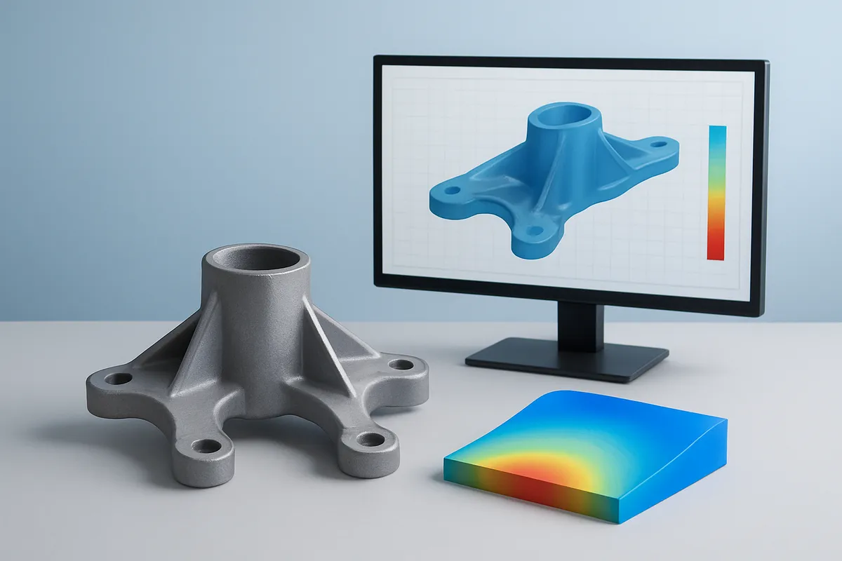
CAD scaling tools and casting simulation software let engineers model shrinkage allowances in die casting digitally, catching dimensional problems before a single block of tool steel is cut.
Neither tool replaces engineering judgment. They narrow the range of likely outcomes so the trial-and-error phase gets shorter, not eliminated.
Which Software Platforms Do Precision Die Casting Engineers Use to Model Shrinkage Before Tooling?
Most CAD packages used in tool design include a non-uniform scaling function, which lets an engineer apply different shrinkage compensation rates to different regions of the same part model instead of one blanket factor across the whole geometry. A thin wall section and a thick boss on the same casting rarely shrink at the same rate, so scaling them identically guarantees one of the two ends up out of tolerance. Non-uniform scaling builds that variation into the tool design stage, where it costs a CAD revision instead of a re-cut die.
Above that entry-level scaling capability sits a separate category: casting flow and solidification simulation software. These programs model how molten alloy fills the cavity, how the part cools, and where shrinkage porosity or dimensional distortion is likely to form, all before steel is cut. Simulation flags problem areas, a thick section fed too late, a gate placement that starves one corner of the cavity, that a shrinkage table alone would never surface.
The right tier depends on part complexity and tolerance demands, not brand preference: a simple bracket may need only CAD scaling, while a thin-walled housing with tight ±0.001mm callouts justifies full solidification simulation. Either way, simulation supplements alloy shrinkage tables and physical trial shots rather than replacing them, it reduces how many iterations those trial shots require.
Frequently Asked Questions
Is shrinkage allowance the same as machining allowance?
No, they solve different problems and both get built into the same tool. Shrinkage allowance oversizes the cavity to compensate for the metal contracting as it cools, applied uniformly based on the alloy’s shrinkage rate. Machining allowance adds extra stock on specific surfaces that need secondary cutting to hit a tighter tolerance than die casting alone can hold. A drawing may call for both on the same feature.
Why do thicker sections of a die cast part shrink more than thinner sections?
Thicker sections hold heat longer, so they solidify slower and contract more before the surrounding metal locks them in place. Thin walls cool fast against the die surface and stop shrinking sooner. This mismatch is why uniform wall thickness is one of the first design changes we recommend when a part shows inconsistent shrinkage across its cross-section.
Can shrinkage allowance eliminate the need for post-cast machining entirely?
Rarely, for tolerances tighter than standard die casting can hold. Shrinkage allowance controls average dimensional change, but variables like porosity, gate location, and die wear still cause part-to-part variation. Features needing tolerances near ±0.001mm, such as bearing bores or sealing surfaces, typically still require CNC finishing after casting.
How much does die temperature alone change shrinkage on a typical aluminum die casting?
Die temperature shifts shrinkage by a measurable margin, though the exact figure depends on alloy, wall thickness, and cooling channel design. A hotter die slows solidification and reduces the metal’s total contraction, while a cooler die accelerates freezing and increases shrinkage. Toolmakers verify this empirically with first-article inspection rather than relying on shrinkage-rate tables alone, since real production conditions rarely match theoretical assumptions exactly.
Do shrinkage allowances die casting engineers use ever need updating after a tool is already in production?
Yes, if the tool shows a consistent dimensional drift that first-article inspection didn’t catch, or if the customer’s alloy specification changes mid-program. Die wear, changes in cooling channel performance over time, and switching to a different supplier’s alloy chemistry can all shift real-world shrinkage enough to warrant re-verifying the original allowance against current production data.
Conclusion
Getting shrinkage allowance right comes down to three things: start with the alloy’s published shrinkage rate, adjust it for wall thickness and geometry rather than applying one number across the whole part, and confirm the result with first-article inspection before committing to production tooling. Skipping that verification step is where most dimensional disputes originate. If you’re specifying tooling for a new part, request a shrinkage and tolerance review before cutting steel, GC INDUS runs this check as part of tooling design for die-cast components across aluminum, magnesium, and zinc, backed by ISO 9001 inspection protocols and tolerances down to ±0.001mm on finished parts.
Recommended Articles
Explore more from our content library:


