
Book Appointment Now

GC INDUS / MANUFACTURING KNOWLEDGE
What Is DFM (Design for Manufacturability) and Why It

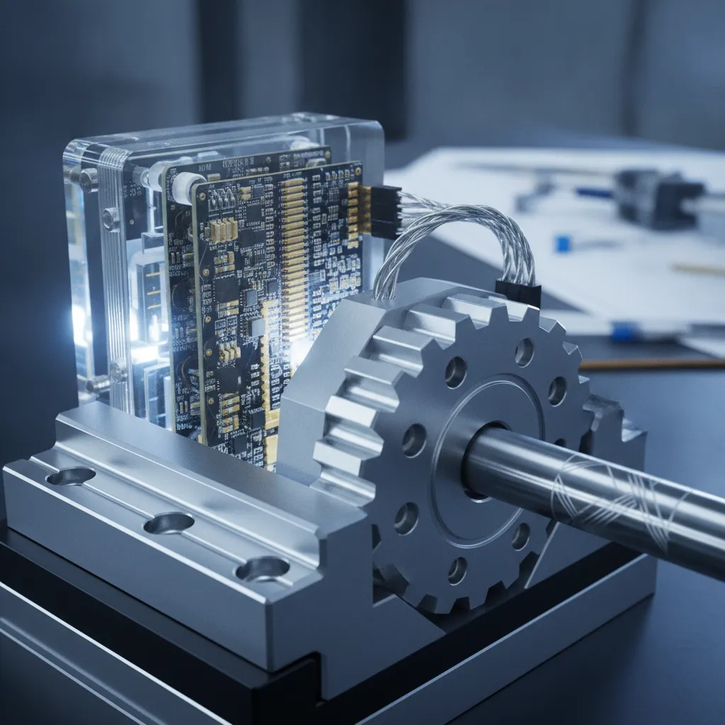
Understanding design for manufacturability precision is essential. Design for manufacturability (DFM) in precision manufacturing means engineering parts so they can be produced consistently, accurately, and economically, without sacrificing dimensional integrity. Precision matters because tight tolerances leave no room for design choices that complicate machining, inflate scrap rates, or extend lead times. Applied early, DFM aligns geometry, material selection, and tolerance callouts with what a given process can reliably hold, cutting rework and shortening the path from drawing to finished part.
What Is Design for Manufacturability Precision and Why Does It Matter?
DFM shapes geometry, materials, tolerances, and features around what a manufacturing process can reliably produce, not just what the finished part must do.
Design for manufacturability precision treats the drawing as a manufacturing instruction, not just a functional specification. Every callout, a radius, a surface finish, a positional tolerance, carries a production consequence. When designers account for those consequences before the first setup, parts move through machining, inspection, and assembly with fewer interruptions.
Precision amplifies the stakes considerably. At tolerances of ±0.001mm, a single over-specified callout can force a process change, shifting from standard CNC milling to EDM or grinding, add setups, or make a feature unmachineable on standard equipment altogether. The tighter the tolerance, the more expensive each design assumption becomes when it turns out to be wrong.
The cost-of-change curve makes this concrete. A design revision during concept development costs a fraction of the same change made after tooling is cut or a first article inspection fails. DFM must begin at the drawing stage precisely because the window for low-cost correction closes fast once production preparation starts.
How Does DFM Differ from DFMA?
DFM focuses on individual part producibility, whether a single component can be manufactured accurately and efficiently. DFMA (Design for Manufacturing and Assembly) extends that lens to how multiple parts fit and assemble together. When a product involves sub-assemblies, DFMA adds a second layer of analysis: joint access, fastener standardization, and assembly sequence all affect total production cost in ways that single-part DFM does not address.
Both disciplines are complementary. A part can be individually producible yet difficult to assemble at scale, which is why sub-assembly work benefits from both reviews running in parallel.
Key DFM Standards for Aerospace and Medical Manufacturing
Aerospace, medical devices, and defense are the industries where design for manufacturability precision is non-negotiable. In these sectors, out-of-tolerance parts are not rework candidates, they are rejections, and in regulated applications, they are compliance failures.
Each industry carries its own standards framework. Aerospace suppliers work within AS9100 quality management requirements, which tie design and production controls together explicitly. Medical device manufacturers operate under ISO 13485, the standard that governs quality systems for medical device production, a certification GC INDUS holds, covering the full production chain from machining through inspection. Geometric dimensioning and tolerancing (GD&T) and ISO 13715 surface texture indication provide the shared language that connects design intent to inspection criteria across both sectors.
These standards do not replace good DFM judgment, they formalize it. A drawing that meets GD&T conventions but specifies tolerances a standard machining center cannot hold still fails the DFM test, regardless of regulatory compliance.
Core DFM Principles That Reduce Cost in Precision Manufacturing
Four principles drive most of the cost reduction in design for manufacturability precision work: simplification, standardization, process alignment, and material selection.
How Simplification Reduces Design Complexity and Lead Times
Reducing feature count is the highest-use move a design team can make. Every unnecessary undercut, pocket, or compound angle adds a setup, a fixture, or a tool change—each one introduces variation and extends the production schedule. A part that requires three setups instead of five is not just faster to machine; it accumulates less positional error across those operations.
Simplification also compresses inspection. Fewer geometric features mean fewer checkpoints, which shortens the time between machining and delivery. At GC INDUS, where full inspection protocols are standard, a simpler part moves through dimensional verification faster without sacrificing the rigor that ISO 9001 requires.
Standardizing features compounds those gains. Specifying hole diameters, thread sizes, and corner radii that match off-the-shelf tooling eliminates custom tool procurement—a delay that can add days or weeks to a production cycle. Using a 6mm radius instead of a 5.7mm radius is a trivial design change that removes a special-order cutter from the bill of materials entirely.
Process alignment prevents mid-production substitutions. A deep, narrow pocket that milling cannot clear cleanly may require EDM wire cutting—a capable process, but one that adds a separate machine queue. Designing the pocket geometry to suit the primary process from the start keeps the part on a single workcell.
Material selection is equally a DFM decision. A material’s machinability rating, thermal expansion coefficient, and surface finish response all determine whether a part can hold its specified tolerance without secondary operations. Choosing an aluminum alloy that machines cleanly at ±0.001mm is a design call that prevents rework downstream—not just a mechanical engineering preference. For more information, see Design Engineer.
How to Optimize Tolerances and Features for Precision Manufacturing
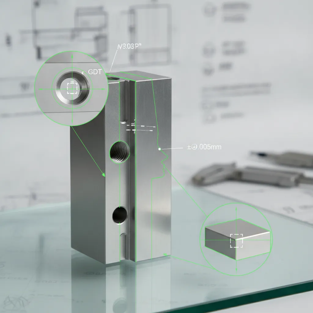
Tolerance optimization means tightening callouts only where fit, function, or safety demands it—every unnecessary tight tolerance adds inspection steps, slows cycle time, and raises scrap rates.
The principle of functional tolerancing is straightforward: if a dimension doesn’t govern how a part fits its mating component or performs its safety-critical role, it doesn’t need a tight callout. Applying ±0.001mm across an entire drawing when only two mating bores require it forces the machinist to treat every feature as a precision surface—multiplying setup time and inspection burden without improving part performance.
GD&T (Geometric Dimensioning and Tolerancing) communicates design intent more precisely than coordinate tolerancing. By specifying form, orientation, and position controls directly on the features that matter, GD&T prevents over-inspection of non-critical geometry and eliminates the ambiguity that causes machinists to default to the tightest possible interpretation of a drawing.
Tolerance Optimization Strategies by Manufacturing Process
Each process carries a natural tolerance band. CNC milling and turning typically hold ±0.01mm to ±0.05mm in standard production; grinding and EDM wire cutting reach ±0.002mm to ±0.005mm without secondary operations. Designing to the natural capability of the chosen process—rather than specifying tighter tolerances and relying on a secondary grinding pass—keeps the part on a single machine and cuts lead time.
Feature design rules matter just as much as tolerance callouts. Minimum wall thickness should be sized relative to material stiffness—thin aluminum walls below 0.8mm deflect under cutting forces and produce out-of-tolerance parts. Pocket radius-to-depth ratios above 1:4 become difficult to clear with standard end mills. Thread engagement length should be at least 1.5 times the nominal diameter in aluminum to prevent pull-out under load. These are features that are geometrically possible in CAD but practically unmachineable without redesign.
Applying design for manufacturability precision principles at the tolerance and feature level is where GC INDUS engineers engage during DFM review—flagging callouts that force EDM or grinding when CNC turning is sufficient, and recommending standard radii that match available tooling.
DFM Constraints in Additive Manufacturing and Hybrid Processes
Additive manufacturing introduces a different set of DFM constraints that must be designed in from the start, not addressed after a build fails. Layer orientation determines both mechanical anisotropy and surface finish—features printed parallel to the build plate have different strength characteristics than those built vertically. Support structure placement must be planned before the file is sent to the printer; supports that contact functional mating surfaces create post-processing rework that erases the speed advantage of additive.
Mating surfaces, bearing bores, and threaded interfaces on additively manufactured parts almost always require a machining step after printing. Designing those surfaces with machining stock—typically 0.3mm to 0.5mm—and accessible tool paths from the start prevents the part from arriving at the CNC stage unmachineable. Heat treatment for metal additive parts must also be sequenced before final machining to avoid distortion that invalidates finished dimensions.
Common DFM Mistakes in Precision Parts and How to Avoid Them
The most damaging design for manufacturability precision errors are over-tolerancing, poor tool access, and late manufacturing reviews—each preventable with early collaboration.
Over-Tolerancing
Specifying tighter tolerances than the function actually demands forces the manufacturer into slower cutting speeds, additional inspection stages, and higher scrap rates. A tolerance of ±0.001mm is achievable—GC INDUS holds it routinely—but applying it to non-critical surfaces adds cost with no functional return. A tolerance audit that maps each callout to a specific functional requirement will expose where standard tolerances can replace tight ones without affecting part performance.
Ignoring Tool Access
A feature that looks clean in CAD can be unmachineable when a physical cutting tool cannot reach it. Deep slots with no relief, blind holes lacking exit geometry, and internal sharp corners are the most common offenders. No amount of machine capability resolves a geometry that blocks the tool path—the design itself must change.
Late DFM Review
Waiting until a design is finalized before engaging manufacturing is the costliest mistake. By that point, tooling may be ordered, fixturing designed, and raw material on order. Changes at that stage disrupt all three simultaneously, compressing schedules and inflating cost.
How to Resolve Conflicts Between Design Intent and Manufacturing Constraints
Work through conflicts in a defined sequence. First, identify whether the conflict is tolerance-driven, geometry-driven, or material-driven. Second, assess whether the functional requirement can be met with a relaxed callout. Third, evaluate process substitution—EDM wire cutting, for example, can reach geometries that milling cannot. Fourth, escalate to a formal design review with manufacturing input before any tooling is committed.
Resolving these conflicts requires a shared technical language, not informal negotiation. GD&T callouts, process capability data, and first article inspection results give both engineering and manufacturing teams a common reference point—one that removes ambiguity and makes the resolution traceable.
How to Measure DFM Success and Apply It Across Industries
DFM success shows up in four numbers: first-article acceptance rate, scrap and rework rate per part number, engineering change orders raised after release, and production cycle time against target.
When those metrics move in the right direction—higher acceptance rates, fewer ECOs, shorter cycle times—design for manufacturability precision is working. When they don’t, the data points directly to where the design-to-production handoff broke down.
DFM Tools and CAD Integration for Simulation and Analysis
CAD-integrated DFM analysis tools flag problems before a drawing is released. They identify unmachineable features, tolerance stack-up conflicts, and non-standard geometry that would otherwise surface as scrap on the shop floor.
Simulation at the design stage is particularly valuable for tight-tolerance work. A tolerance stack-up that looks acceptable on a single-part drawing can cause assembly failures when three or four components interact—software catches this before any material is cut.
The output of a DFM tool review should feed directly into the engineering change order process. Any flagged issue that requires a design modification gets documented, resolved, and re-checked before release—reducing the ECO count that would otherwise accumulate post-production.
Industry-Specific DFM Applications: Aerospace, Medical, and Consumer Parts
DFM emphasis shifts significantly depending on the regulatory environment and production volume of the end market.
Aerospace DFM operates under AS9100 quality management requirements, where traceability and inspectability are non-negotiable. Every feature must be measurable, every tolerance must be justified, and the consequence of a field failure drives conservative design decisions throughout. No feature is included unless it can be verified.
Medical device manufacturing adds another layer: ISO 13485 and FDA design controls require documented design reviews that include manufacturability assessments. DFM is not a recommended practice here—it is a regulatory checkpoint. GC INDUS holds ISO 13485 certification, which means manufacturability reviews are built into its quality process rather than bolted on at the end.
Consumer and industrial manufacturing shifts the DFM focus toward cycle time reduction, tooling amortization, and assembly simplification. Traceability demands are lower, but cost pressure is higher—so DFM decisions center on part consolidation, standard feature geometry, and minimizing secondary operations across high-volume runs.
Frequently Asked Questions
At what stage of product development should DFM analysis happen?
DFM analysis should begin during the concept and early design phase, before detailed drawings are finalized. Changes made at the concept stage cost a fraction of what they cost once tooling is ordered or production has started. The further a design progresses without manufacturing input, the more expensive and disruptive any corrections become—a pattern engineers in medical device and aerospace programs encounter repeatedly.
What is the difference between DFM and design for assembly (DFA)?
DFM focuses on making individual parts easier to manufacture, while DFA focuses on reducing the time and complexity of assembling those parts together. The two disciplines overlap significantly—a part designed for easier machining often also assembles with fewer steps. DFMA combines both into a single review process, which is the approach most contract manufacturers apply when evaluating a full assembly rather than isolated components.
How does DFM apply to low-volume or prototype precision parts?
DFM applies directly to low-volume and prototype work—often with greater impact than in high-volume production. When order quantities are small, there is no volume over which to spread the cost of a design flaw, so a single out-of-tolerance feature can make a prototype run uneconomical. GC INDUS accepts orders from 1 piece, which means DFM review at the prototype stage directly protects the economics of early iterations before production commitments are made.
Can DFM principles be applied to parts made from difficult-to-machine materials like titanium or Inconel?
Yes—DFM is especially valuable for difficult-to-machine materials because machining time and tool wear are significantly higher than with aluminum or mild steel. Applying DFM to a titanium part means minimizing deep cavities, avoiding unnecessarily tight tolerances in non-functional areas, and selecting feature geometries that reduce cutting passes. These decisions can meaningfully reduce cycle time and scrap rates without changing the part’s functional performance. The same logic applies to Inconel and other high-temperature alloys.
Conclusion
Design for manufacturability in precision engineering is not a final check before production—it is a decision-making discipline that runs from the first sketch to the finished part. The clearest takeaways: tolerances should reflect functional requirements, not default drawing conventions; feature geometry should match the cutting tools and processes that will actually produce the part; and manufacturing input should enter the design process early, when changes are still inexpensive.
If you have a design approaching the prototype or production stage, submit your CAD file to GC INDUS for a DFM-informed quote. The review will identify tolerance, geometry, or material choices that affect cost or lead time before they become problems on the shop floor.
Recommended Articles
Explore more from our content library:


