
Book Appointment Now

GC INDUS / MANUFACTURING KNOWLEDGE
Electrical Discharge Machining Precision for Complex Shapes

Electrical discharge machining precision refers to the ability of EDM to remove material through controlled electrical sparks, achieving tolerances as tight as ±0.001mm on hardened metals and complex geometries that conventional cutting tools cannot reach. Because the electrode never contacts the workpiece, there is no cutting force to deflect thin walls or delicate features. This makes EDM the preferred process for mould cavities, aerospace components, and medical implants where dimensional accuracy is non-negotiable.
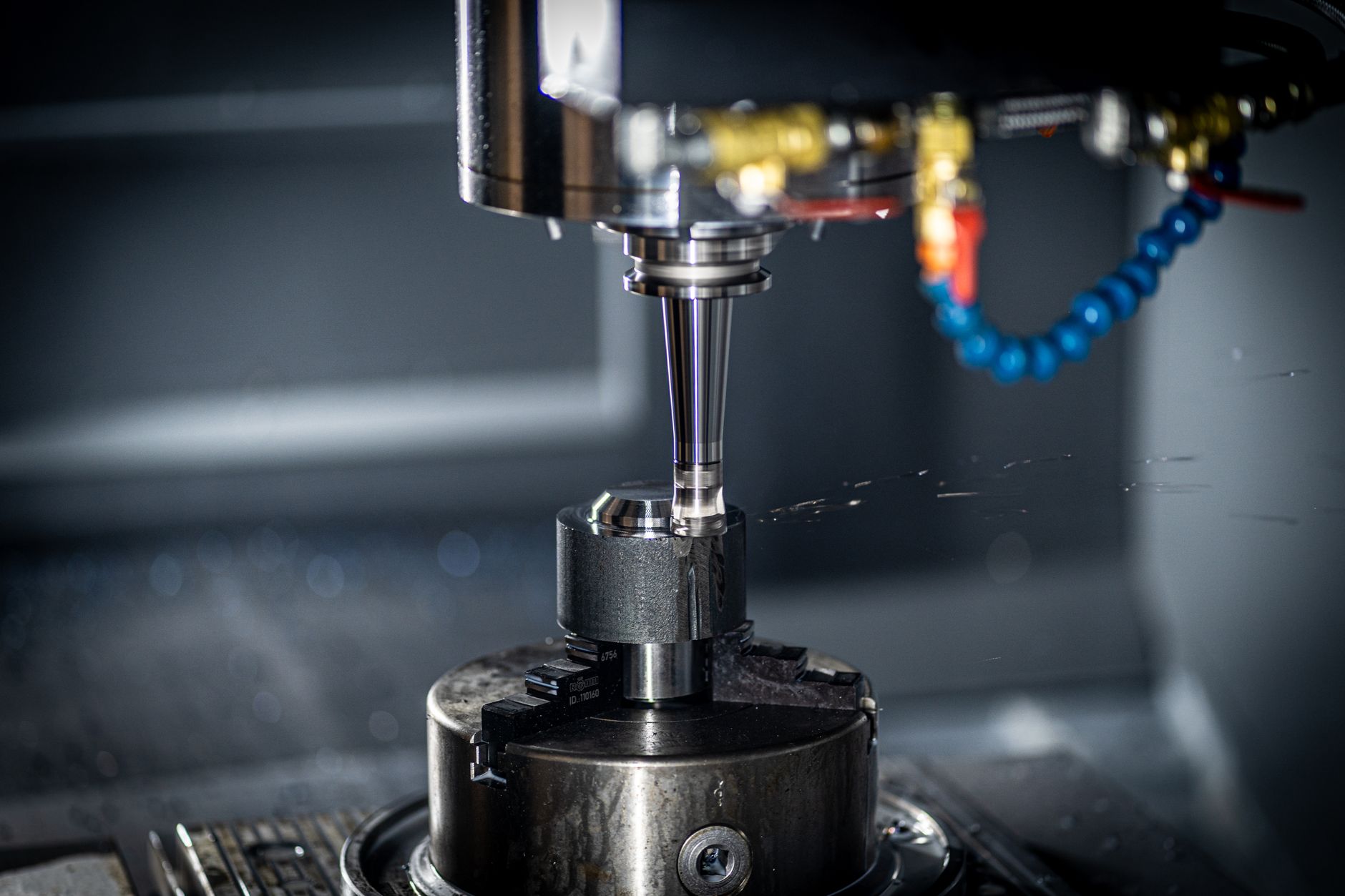
What Is Electrical Discharge Machining Precision and How Does EDM Achieve It?
EDM achieves its precision by eroding material one microscopic spark at a time, with no physical contact between the tool and the workpiece. For a detailed technical overview of the process, see the Electrical discharge machining article on Wikipedia.
The material removal mechanism that makes EDM so precise
The process works by passing a controlled electrical voltage across a narrow gap between an electrode and the workpiece, both submerged in a dielectric fluid, typically deionized water or hydrocarbon oil. When the voltage reaches a threshold, a spark discharges across the gap, vaporizing a tiny amount of workpiece material. The dielectric fluid then flushes the debris away and quenches the plasma channel before the next pulse fires.
Each discharge removes material in increments measured in microns. Because no cutting tool ever touches the part, there are no mechanical forces to deflect thin walls, distort sharp internal corners, or stress a hardened workpiece. That absence of contact force is the root cause of electrical discharge machining precision — the part holds its geometry throughout the cut regardless of how hard or brittle the material is.
Precision is also built directly into the process parameters. Engineers control discharge energy, pulse duration, and gap voltage to dial in the material removal rate and surface finish. Tighter pulse settings produce finer surface textures and smaller dimensional variation, independent of the machine’s mechanical stiffness.
Sinker EDM vs wire EDM: precision capabilities compared
The two main EDM types use different electrode geometries, and that difference determines which features each process handles best.
Sinker EDM, also called die-sinking EDM, uses a shaped electrode — typically machined from graphite or copper — that plunges into the workpiece to form a cavity matching the electrode’s inverse profile. This makes it the preferred method for blind pockets, complex mould cavities, and internal contours that a wire cannot reach.
Wire EDM uses a continuously fed metal wire, usually brass, as the electrode. The wire cuts a narrow kerf through the workpiece along a programmed path, making it ideal for through-profiles, punches, dies, and parts requiring extremely tight angular tolerances on vertical walls. Because the wire is constantly renewed, electrode wear does not accumulate and degrade dimensional accuracy over a long cut.
Both types share the same non-contact erosion principle, but the electrode geometry determines the feature types each can hold to the tightest tolerances. The table below summarises the key differences at a glance:
- Sinker EDM: shaped graphite or copper electrode; best for blind pockets, mould cavities, and complex 3D internal contours
- Wire EDM: continuously fed brass wire; best for through-profiles, punches, dies, and tight angular tolerances on vertical walls
- Shared advantage: non-contact erosion eliminates cutting forces and allows machining of fully hardened workpieces
- Key distinction: wire EDM self-renews the electrode, preventing cumulative wear; sinker EDM requires electrode management strategies
How EDM Precision Compares to CNC Machining, Laser Cutting, and Grinding
EDM outperforms CNC milling, laser cutting, and grinding on hardened materials and complex geometries, but each process leads in specific conditions. For a broader perspective on EDM’s precision capabilities in practice, TTH’s exploration of precision electrical discharge machining provides useful real-world context.
Precision Advantages and Disadvantages of EDM Versus Grinding and Conventional Machining
CNC milling applies cutting forces directly to the workpiece. On hardened tool steel or thin-walled parts, tool deflection, vibration, and chip load combine to create tolerance stack-up that can push finished dimensions outside acceptable limits. Electrical discharge machining precision sidesteps this entirely — the electrode never contacts the workpiece — so there is no cutting force and no mechanical distortion.
Laser cutting introduces a heat-affected zone (HAZ) along every cut edge. The thermal gradient alters the surface microstructure and causes dimensional drift in the material immediately adjacent to the kerf. EDM’s thermal influence is confined to the controlled spark gap, typically measured in microns, which keeps metallurgical changes localized and predictable.
Precision grinding matches or exceeds EDM on surface finish for flat and cylindrical surfaces, routinely achieving Ra values below 0.1 µm on the right setup. The limitation is geometry: grinding wheels cannot produce internal sharp corners, deep narrow slots, or complex 3D cavities. Sinker EDM can machine all three.
Applications Where EDM Outperforms Alternative Machining Methods
EDM is the stronger choice in four specific scenarios: For more information, see Viticulture De Precision En Medoc Guide Complet.
- Deep narrow slots where a milling cutter would deflect or break under cutting forces
- Hardened tool steel cavities that would blunt a carbide end mill within minutes
- Micro-features with corner radii below 0.1 mm that grinding wheels cannot replicate
- Internal geometries — such as blind pockets and undercuts — that no rotating tool can reach
CNC milling and grinding remain more efficient for softer materials, open surfaces, and high-volume stock removal. EDM’s slower material removal rate makes it a poor choice when geometry permits conventional cutting, but when geometry or hardness rules that out, EDM is often the only viable path.

What Factors Affect EDM Precision and What Are the Real-World Tolerance Limits?
Electrical discharge machining precision is controlled by discharge energy, pulse timing, electrode wear, and environmental stability — each variable shifts where a finished part lands relative to nominal.
Technological parameters that control precision in electrical discharge machining
Discharge energy is the most direct lever. Lower energy per spark produces a finer surface finish and tighter dimensional control, but it also slows material removal — so manufacturers trade cycle time against accuracy based on part requirements.
Pulse-on time determines how long each spark contacts the workpiece. Shorter pulses remove less material per cycle and leave a shallower recast layer, which keeps surface geometry closer to the intended form. Flushing pressure matters equally: insufficient dielectric flow lets debris accumulate in the gap, causing secondary discharges that erode the workpiece unevenly.
Electrode wear is the primary source of dimensional error in sinker EDM. As the electrode erodes, it stops replicating the intended cavity geometry accurately. Manufacturers manage this through three approaches: selecting electrode materials with favorable wear ratios (graphite or copper-tungsten), running multiple electrodes in sequence so each finishes a portion of the cut, and applying adaptive CNC correction that adjusts tool-path offsets as wear progresses.
How precision degrades in production environments
Single-part setups in a temperature-controlled environment can achieve tolerances approaching ±0.005 mm under ideal conditions. Production runs introduce three additional error sources: thermal drift in the machine structure as the frame heats over a shift, dielectric temperature variation that changes the fluid’s electrical resistance and alters spark behavior, and workpiece fixturing that flexes under repeated loading.
Each mechanism pushes results away from the theoretical limit. Without active process monitoring — closed-loop feedback on gap voltage, fluid temperature, and electrode position — tolerance bands widen as batch size and cycle time increase. A part made in hour one of a run may hold a tighter tolerance than the same part made in hour eight. Implementing consistent dielectric temperature control and periodic electrode checks between batches are among the most effective countermeasures available to production teams.
How Manufacturers Measure and Verify EDM Precision in Production
EDM precision is confirmed through CMM inspection, surface profilometry, real-time machine monitoring, and structured sampling protocols applied across the production run.
Quality Control Methods and Precision Measurement Techniques for EDM Tolerances
Coordinate measuring machine (CMM) inspection is the primary post-process verification tool for EDM parts. A CMM probe maps hundreds of points across a finished cavity or electrode geometry, comparing each measured coordinate against the CAD nominal to calculate dimensional deviation — catching errors in depth, wall angle, and corner radius that visual inspection cannot detect.
Surface profilometry confirms that Ra finish values meet specification. Because surface roughness is directly tied to the discharge energy settings used in the EDM finishing pass, a profilometer reading that falls outside the target Ra range signals that the final spark parameters need adjustment — not that the part requires rework by default.
In-process monitoring adds a real-time layer of control. Modern EDM machines continuously log gap voltage and discharge frequency. When those values drift — due to electrode wear or inadequate flushing of debris — the machine flags the condition before an out-of-tolerance feature is cut, reducing scrap and unplanned rework.
First-article inspection (FAI) validates the full dimensional report on the first confirmed-good part before a production run begins. Once FAI passes, statistical process control (SPC) sampling governs the batch — measuring a defined subset of parts at set intervals to maintain tolerance confidence without inspecting every piece. GC INDUS applies full inspection protocols across EDM production, holding tolerances to ±0.001mm under its ISO 9001 and ISO 13485 certified quality system.
When Does EDM Precision Justify the Cost Over Conventional Machining?
EDM becomes the economically rational choice when part geometry, material hardness, or tolerance requirements make conventional machining impractical or cost-prohibitive.
EDM’s slower material removal rate and electrode tooling costs look expensive on a per-hour basis. That comparison shifts when the alternative involves multiple setups, specialized grinding fixtures, or high scrap rates on hardened tool steel. A single EDM cycle that holds ±0.005mm on a hardened workpiece often costs less in total than three conventional setups that still risk dimensional drift.
Certain features remove the cost comparison entirely. Deep narrow slots in hardened steel, blind cavities with sharp internal corners, and fine through-holes in heat-treated components cannot be produced reliably by milling or grinding. When a feature has no conventional alternative, electrical discharge machining precision is the only path — not a premium one.
Industries That Benefit Most from EDM Precision
Aerospace manufacturers rely on EDM for turbine blade cooling holes and fuel system components where burr contamination is a flight safety issue. Medical device producers use it for implant geometries that require burr-free surfaces without secondary finishing, a requirement that aligns directly with ISO 13485 quality standards. Injection mold toolmakers depend on EDM cavity surface finish because any texture defect transfers directly to every molded part — scrap compounds across the entire production run.
When part complexity, material hardness, and tolerance requirements converge, EDM moves from a premium option to the lowest total-cost path. Eliminating rework and scrap across a production run routinely offsets the higher per-cycle time. GC INDUS applies EDM alongside CNC milling, grinding, and Swiss lathe turning so the right process handles each feature — keeping both quality and cost under control.

Frequently Asked Questions
Can EDM machine non-conductive materials?
EDM requires electrical conductivity in the workpiece — it cannot machine non-conductive materials like ceramics, glass, or most plastics in standard form. Researchers have developed hybrid techniques, such as coating non-conductive surfaces with a conductive layer, but these remain specialized and are not standard shop-floor practice. For non-conductive components, processes like CNC milling or grinding are the appropriate choice.
What surface finish can EDM achieve and how is it controlled?
EDM can produce surface finishes ranging from roughly Ra 0.1 µm in fine finishing passes down to Ra 3–4 µm in roughing cuts, depending on discharge energy settings. Lower peak current and shorter pulse duration reduce crater size on the workpiece surface, producing a finer finish. Operators typically run multiple passes, starting with high-energy roughing to remove bulk material, then progressively reducing energy to refine the surface.
How does wire EDM differ from sinker EDM in terms of the geometries each can produce?
Wire EDM uses a continuously moving wire electrode to cut 2D profiles and tapered through-cuts, while sinker EDM uses a shaped electrode to erode 3D cavities into a workpiece. Wire EDM excels at producing precise slots, gears, and contoured blanks from plate stock. Sinker EDM is the right choice for blind pockets, complex mold cavities, and internal features that a wire cannot reach.
Does EDM leave a heat-affected zone on the workpiece surface?
EDM does produce a thin heat-affected zone (HAZ) and a recast layer, typically just a few micrometers deep, where the surface material melted and resolidified during sparking. This layer can be harder and more brittle than the base material. For fatigue-critical or high-precision applications, a light finishing pass or post-process polishing removes the recast layer and restores surface integrity.
How does material hardness affect EDM precision?
Unlike conventional cutting, EDM precision is largely independent of workpiece hardness — the spark erodes material through thermal energy, not mechanical force, so fully hardened tool steels and carbides machine just as accurately as softer alloys. This is one of EDM’s most significant advantages: parts can be hardened before machining, eliminating the dimensional distortion that heat treatment introduces after conventional milling. The main consideration is that harder materials may require slightly adjusted discharge parameters to maintain optimal flushing and surface finish.
Conclusion
Electrical discharge machining precision comes down to three controllable factors: discharge energy, electrode condition, and dielectric management. Get those right, and EDM consistently holds tolerances that conventional cutting tools cannot match in hardened materials or complex geometries.
Two actions are worth prioritizing. First, match the EDM variant — wire or sinker — to the geometry your part actually requires before committing to tooling. Second, specify recast layer removal in your finishing sequence if the part will face cyclic loading or tight surface integrity requirements.
If your next component calls for EDM alongside CNC milling, grinding, or surface treatment, request a fast quote from GC INDUS with your STEP file — our team will review tolerances and process routing in a single conversation.
Recommended Articles
Explore more from our content library:


