
Book Appointment Now

GC INDUS / MANUFACTURING KNOWLEDGE
What Is GD&T and Why It Matters for Engineering Drawings

Understanding what is GD&T is essential. GD&T (Geometric Dimensioning and Tolerancing) is a symbolic language used on engineering drawings to define the allowable variation in a part’s form, size, orientation, and location relative to its intended function. Instead of relying on plus-or-minus linear tolerances alone, GD&T uses standardized symbols, like flatness, position, and runout, tied to datums so every engineer, machinist, and inspector interprets the design intent the same way. Anyone asking what is GD&T for the first time is really asking how a drawing can communicate function, not just numbers. This reduces scrap, rework, and disputes between design and manufacturing teams by removing ambiguity from how tolerances are measured and verified.
What Is GD&T and Why Do Manufacturers Need It?
GD&T is the standardized symbolic system defined in ASME Y14.5 for specifying a part’s allowable form, orientation, location, and runout relative to fixed reference points called datums. Anyone answering what is GD&T at a technical level has to start with that standard, it’s the rulebook that tells a machinist, quality inspector, and design engineer exactly how to read a drawing the same way, every time.
Before ASME Y14.5, drawings relied on coordinate tolerancing, a box of plus-or-minus numbers stacked on X and Y dimensions. That approach leaves gaps: it doesn’t define how round a hole must be, how flat a surface must sit, or how one feature relates to another when both carry independent tolerances. GD&T closes those gaps by attaching tolerance zones to the features that actually matter for function, a mounting hole’s position relative to a datum face, for example, rather than its raw coordinate location. This is particularly relevant for what is GD&T.
What Is Rule #1 in GD&T and Why Does It Matter?
Rule #1, the envelope principle, states that a feature’s size tolerance also governs its form, a shaft machined at its maximum material size must be perfectly cylindrical along its full length. This matters because a part can pass every individual size check with calipers and still fail to assemble if it’s bowed, tapered, or out-of-round within that size window. Without Rule #1 spelled out on the print, a machinist and an inspector can disagree on whether a bent but “in-tolerance” shaft is acceptable. With it, the pass/fail criteria are fixed to the drawing, not to interpretation.
What Are the Real-World Benefits of GD&T for Precision Manufacturing?
Shops that machine to GD&T prints see fewer scrapped parts because tolerance zones match how the part actually functions, not an arbitrary coordinate grid. Inspection criteria become objective, a CMM report either shows the feature inside its position tolerance or it doesn’t, cutting the back-and-forth emails between design and production over what “close enough” means.
Manufacturers need this most when parts have to interchange across suppliers, fixtures, or machines without hand-fitting. Functional gauging built around GD&T datums lets a part machined in one facility mate correctly with a part machined in another, which is exactly the kind of consistency OEM and medical device buyers expect when they qualify a new supplier. At GC INDUS, holding tolerances as tight as ±0.001mm on CNC-machined components depends on reading GD&T callouts correctly before the first cut, not catching a datum misinterpretation after final inspection.
How Does GD&T Reduce Communication Gaps Between Teams?
A design engineer, a CNC programmer, and a quality inspector each look at the same print from a different angle. The engineer cares about function, the programmer cares about achievable process capability, and the inspector cares about measurable pass/fail criteria. GD&T gives all three the same vocabulary, so a position tolerance means the same thing in a CAD annotation, a CAM setup sheet, and a CMM report. That shared vocabulary is a big part of what is GD&T’s practical value beyond the drawing itself, it shortens the loop between a question on the shop floor and a confirmed answer from engineering.
How Do GD&T Symbols Work and What Do the 14 Main Symbols Mean?
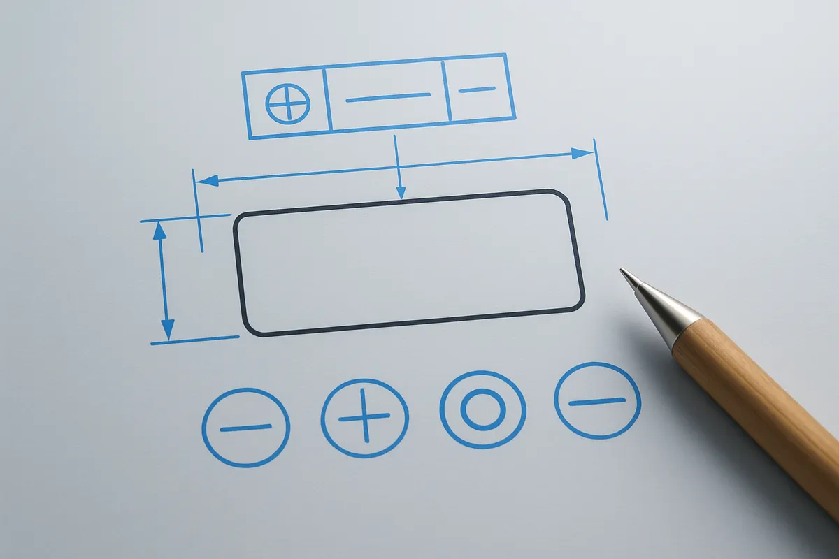
Each GD&T symbol sits inside a feature control frame that reads left to right as symbol, tolerance value, modifiers, then datum references, a fixed grammar you learn once and reuse. Understanding what is GD&T on a practical level starts with learning to parse that frame, because the same symbol means something different depending on which boxes surround it.
How Do You Read and Interpret GD&T Symbols on a Drawing?
A feature control frame is a rectangular box divided into compartments, and each compartment answers a specific question about the toleranced feature. The first box holds the geometric symbol itself, flatness, position, runout, whatever applies. The next box states the tolerance zone value, sometimes preceded by a diameter symbol if the zone is cylindrical rather than a flat band. When considering what is GD&T, this point stands out.
After the tolerance value come modifiers like MMC (maximum material condition) or LMC (least material condition), shown as circled M or L. These modifiers tell the machinist that the tolerance can grow as the feature departs from its worst-case size, a detail that affects gauge design and inspection method, not just the drawing note. The final compartments list datum references, usually one to three letters, in order of precedence.
That order matters. A primary datum controls more degrees of freedom than a secondary or tertiary one, and swapping the order changes how the part sits in the inspection fixture. Datums establish the reference frame that gives every symbol its meaning, a position tolerance with no datum reference describes a different, less useful requirement than one that ties the hole pattern back to a mounting face and two locating pins.
What Are the Most Common GD&T Symbols in Aerospace, Automotive, and Medical Device Manufacturing?
ASME Y14.5 organizes the 14 symbols into five categories, and grouping them this way makes them easier to memorize than a flat list.
- Form: flatness, straightness, circularity, cylindricity, control a surface’s shape without referencing any datum.
- Orientation: perpendicularity, angularity, parallelism, control how a feature tilts relative to a datum.
- Location: position, concentricity, symmetry, control where a feature sits relative to datums, with position doing most of the work in modern drawings.
- Profile: profile of a line, profile of a surface, control complex or contoured shapes, with or without datum references.
- Runout: circular runout, total runout, control wobble and taper on rotating parts.
Which symbols dominate depends on the industry. Aerospace drawings lean heavily on position and profile tolerancing because bolted assemblies and aerodynamic surfaces both demand precise, datum-referenced control. Automotive drawings favor runout on shafts, pulleys, and brake rotors, since anything that spins needs a tight limit on wobble to avoid vibration and noise. Medical device housings rely on profile tolerancing to control complex enclosure geometry where a snap-fit or sealing surface has to mate correctly every time. For those exploring what is GD&T, this matters.
At GC INDUS, we see this pattern directly across the CNC machining, die casting, and injection molding jobs we run for OEM and medical device clients, a rotating automotive component calls for a different inspection plan than a profile-toleranced medical housing, even when both hold tolerances to ±0.001mm. Reading the feature control frame correctly up front is what keeps that inspection plan accurate downstream.
Why Do Some Symbols Require a Datum and Others Don’t?
Form controls, flatness, straightness, circularity, cylindricity, describe a feature relative only to itself, so they never reference a datum. A surface either sits flat within its own tolerance zone or it doesn’t, independent of anything else on the part. Orientation, location, and most profile controls, by contrast, describe a relationship between the toleranced feature and something else on the part, so they need a datum to define what that “something else” is. Recognizing this split early saves a lot of confusion when learning what is GD&T, because it explains why two symbols that look similar on a drawing can have very different feature control frame structures.
How Does GD&T Compare to Traditional Tolerancing Methods?
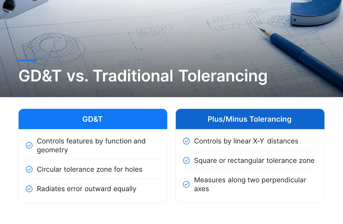
GD&T controls features by their function and geometry, while plus/minus coordinate tolerancing controls them by linear X-Y distances, and that difference decides whether a good part gets rejected on paper.
What Problems Did Manufacturers Face Before GD&T, and How Does GD&T Solve Them?
Coordinate tolerancing measures a hole’s position with a plus/minus value on its X dimension and a separate plus/minus value on its Y dimension. Stack those two together and you get a square or rectangular tolerance zone. But a hole is round, and its position error radiates outward in every direction equally, not along two perpendicular axes. A hole that drifts diagonally, right at the corner of that rectangular zone, can fail inspection under plus/minus rules even though it seats a mating pin without issue. This mismatch between the tolerance zone’s shape and the feature’s actual geometry is the core failure of pre-GD&T dimensioning, and it’s a big part of what is GD&T meant to fix when the ASME Y14.5 standard formalized true position and related controls.
The second failure is stack-up. Linear dimensioning chains tolerances from edge to edge, feature to feature, and each link in that chain adds uncertainty. By the time you reach a part with five or six toleranced dimensions in series, the worst-case variation can be several times larger than any single tolerance on the drawing, a problem covered in more depth in our companion piece on tolerance stack-up. GD&T breaks that chain by referencing features to a defined datum structure, a fixed coordinate system tied to how the part actually mates in assembly, so each feature is controlled relative to a stable reference rather than to the last feature measured.
When Should You Use GD&T Instead of Conventional Tolerancing?
Take a four-hole bolt pattern. Toleranced with plus/minus X-Y coordinates at ±0.13mm on each axis, the acceptance zone is a 0.26mm square. Toleranced with true position at a 0.3mm diameter, the acceptance zone is a circle roughly 36% larger in area, and it matches how a round bolt actually engages a round hole. Parts that would fail the square-zone inspection often pass true position, because they’re functionally fine. This directly impacts what is GD&T outcomes.
Conventional plus/minus tolerancing still has a place. Non-mating features, cosmetic edges, simple brackets with no functional fit requirement, these don’t need a datum structure or feature control frames. At GC INDUS, we apply GD&T selectively: full geometric control on mating and functional features, straightforward linear dimensions everywhere else, which keeps inspection time and drawing complexity proportional to what the part actually needs.
How Does Tolerance Stack-Up Analysis Change Once GD&T Is Introduced?
Traditional stack-up analysis adds and subtracts linear tolerances along a chain of dimensions, which tends to overstate worst-case variation because it assumes every tolerance hits its limit in the same direction at once. GD&T-based stack-up analysis, particularly when paired with statistical tolerancing, models the datum structure directly and accounts for bonus tolerance from MMC or LMC modifiers. The result is usually a more realistic, and often more forgiving, picture of how a stack of tolerances actually behaves in assembly. Engineers deciding what is GD&T worth the extra drawing effort often find the answer in this stack-up comparison alone, since a tighter, more accurate stack-up can eliminate an unnecessary tightening of individual tolerances.
How Do You Apply GD&T Symbols Correctly to Engineering Drawings?
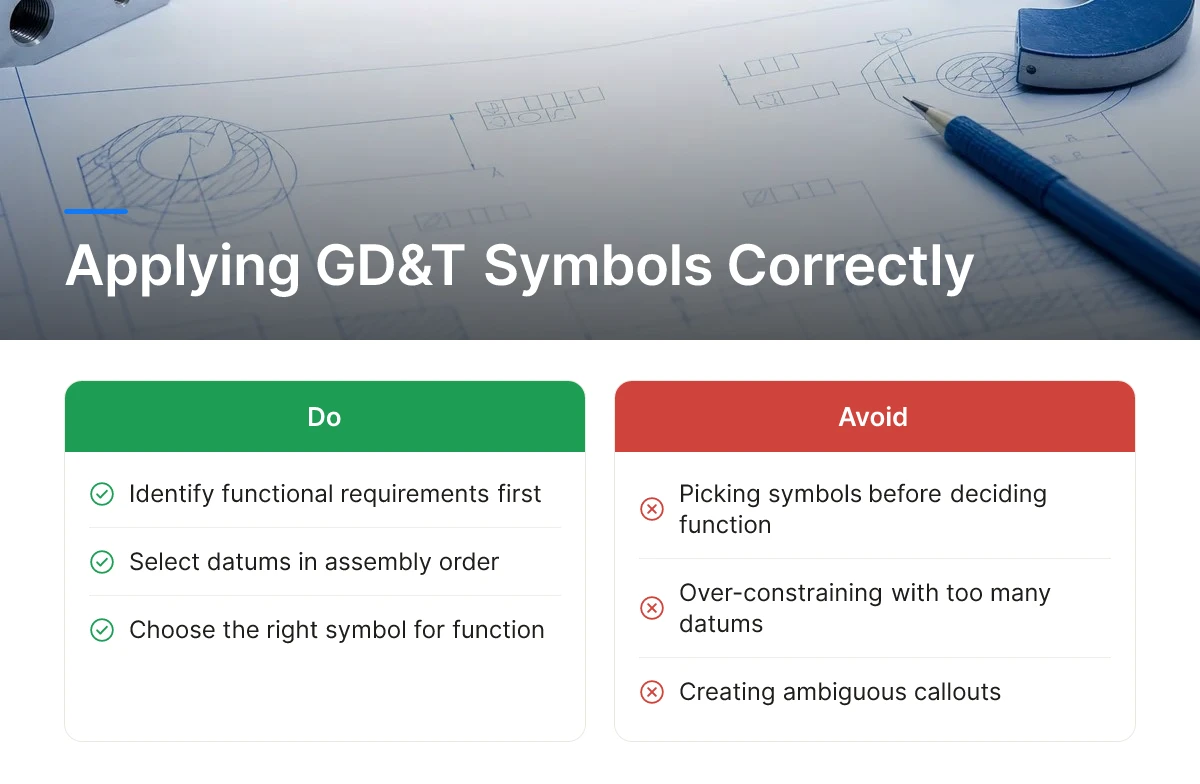
Correct application means identifying the part’s functional requirements first, then selecting datums in assembly order, choosing the right symbol, and building a feature control frame that leaves no room for interpretation.
Getting this sequence backward is where most drawings go wrong. Engineers often pick a symbol before they’ve decided what actually matters to the part’s function, which produces callouts that are technically valid but practically useless on the shop floor.
What Are the Most Common Mistakes Engineers Make When Applying GD&T Symbols?
The most frequent error is over-constraining a part with too many datums, which forces machinists to hold references that don’t matter to fit or function and drives up cost for no functional benefit. A close second is missing datum references entirely, a position or profile callout with no datum structure gives an inspector nothing to measure from. This is particularly relevant for what is GD&T.
- Position tolerance without a required modifier: Omitting a maximum material condition (MMC) modifier when the design intent allows bonus tolerance at larger hole sizes forces tighter-than-necessary inspection and rejects parts that would actually assemble fine.
- Mixing GD&T with conflicting plus/minus dimensions: Placing a ±0.05mm linear tolerance on the same feature that carries a profile or position callout creates two competing standards, and whichever one a machinist or inspector defaults to determines whether the part passes.
- Datum precedence left ambiguous: When the primary, secondary, and tertiary datums aren’t clearly ordered in the feature control frame, two inspectors measuring the same part can set it up on different reference surfaces and get two different results.
That last point is the one that causes the most downstream disagreement. If datum precedence isn’t locked down, a CMM operator and a manual inspector can both follow the drawing correctly and still report different pass/fail outcomes on the same physical part, not because either is wrong, but because the drawing didn’t specify which surface takes priority.
Can You Walk Through a Step-by-Step Example of Applying GD&T to a Precision Part?
Take a mounting bracket that bolts to a housing and locates a bearing bore. The functional requirements are: the bracket must sit flush against the housing, its bolt holes must align with mating threads, and the bore must stay concentric with a mating shaft.
- Identify function first. The flat mounting face controls orientation, so it becomes datum A. The two bolt holes control rotation and location, forming datum B. The bore’s axis is what actually matters for shaft fit.
- Select datums in assembly order. Datum A (primary) constrains the part against the housing face, datum B (secondary) locks rotation, and a tertiary datum can control the last remaining degree of freedom if needed.
- Choose the symbol. Since the bore’s location relative to A and B matters more than its exact diameter, position tolerance with an MMC modifier is the right call, it lets the bore shift slightly as its size grows, without violating fit.
- Build the feature control frame. The frame reads: position symbol, tolerance value, MMC modifier, then datums A, B, C in that order, leaving no question about which surface an inspector references first.
This is what is GD&T actually good for in practice: turning a subjective drawing note into a callout that any qualified inspector reads the same way. At GC INDUS, our quality team checks feature control frames against datum structure before quoting, because an unambiguous callout is what lets incoming inspection at a client’s facility match our own final inspection report without a dispute.
How Do You Verify That a GD&T Callout Is Manufacturable Before Production?
A tolerance that reads cleanly on a drawing isn’t automatically achievable on a given machine or process. Before committing to production, a capable supplier checks the callout against the process’s known capability, verifying that a CNC platform, casting process, or molding tool can consistently hold the specified position or profile tolerance across a full production run, not just on a single sample part. Skipping this feasibility check is how a drawing that looks correct on paper turns into a first-article rejection weeks later. This step is often the real answer to what is GD&T worth before a program launches, since a tolerance nobody can hold in volume isn’t a functional spec, it’s a liability.
What Software and CAD Tools Help Implement GD&T in Manufacturing?
GD&T moves from paper to production through CAD systems that embed tolerance annotations in 3D models, then flows into inspection software that verifies parts against those digital specs automatically.
Understanding what is GD&T on a drawing is only half the job. The other half is making sure that intent survives the trip from design file to shop floor to inspection report without getting lost in translation between departments or software packages.
How Do You Integrate GD&T into Your CAD Workflow and Quality Assurance Process?
Most modern CAD platforms now support model-based definition (MBD), which attaches GD&T callouts directly to the 3D solid model instead of relying solely on a flat 2D drawing. This matters because a 3D annotation travels with the model through downstream processes, CAM programming, simulation, and inspection, without someone re-typing tolerance values into a separate system. When considering what is GD&T, this point stands out.
On the inspection side, that same GD&T data can feed coordinate measuring machine (CMM) software directly. Instead of a technician manually interpreting a feature control frame and setting up a measurement routine by hand, the CMM software reads the annotated model, builds the inspection plan, and reports pass/fail against the actual tolerance zone, position, flatness, profile, whatever the drawing calls out. This is how a shop supports automated first-article inspection and repeatable in-process checks on high-volume runs rather than one-off manual gauging.
At GC INDUS, this kind of digital thread between CAD annotation and CMM verification underpins how we run full inspection protocols across CNC-machined and cast parts, particularly on jobs holding tolerances to ±0.001mm where manual interpretation leaves too much room for error.
Software cost tiers vary widely. Budget-friendly options are often add-ons to existing CAD packages that let designers apply GD&T symbols correctly but stop there, no CMM linkage, no automated reporting. Premium suites integrate MBD authoring, tolerance stack-up analysis, and CMM programming in one connected system, which costs more but removes manual re-entry points where errors creep in. Mid-market teams often mix tools: a CAD add-on for design and a separate metrology package for the inspection floor.
Is GD&T Difficult to Learn, and What Training Does Your Team Need?
GD&T is not something engineers or machinists pick up casually on the job, it requires structured training against the ASME Y14.5 standard to apply consistently and avoid misreading feature control frames. For those exploring what is GD&T, this matters.
Teams building real proficiency typically combine a foundational course covering symbol meaning and datum reference frames, hands-on workshops reading actual production prints, and eventually a recognized certification for anyone signing off on inspection reports. Skipping this step is where quality escapes start, someone assumes a tolerance means one thing when the standard defines it differently.
What Roles on a Manufacturing Team Need the Deepest GD&T Knowledge?
Not everyone touching a drawing needs the same depth of GD&T fluency. Design engineers need the deepest understanding, since they choose datums and symbols in the first place and set the functional intent everyone downstream depends on. CNC programmers and quality inspectors need strong practical fluency, enough to translate a feature control frame into a toolpath or an inspection routine without guessing. Production operators generally need a lighter, targeted understanding, just enough to recognize when a callout affects a setup or fixture choice. Matching training depth to role is a practical way to answer what is GD&T training worth investing in for a given team, rather than sending an entire shop through an identical course.

Frequently Asked Questions
What does GD&T stand for?
GD&T stands for Geometric Dimensioning and Tolerancing, a symbolic language used on engineering drawings to define part geometry and allowable variation. It replaces plain linear dimensions with symbols that describe form, orientation, location, and runout relative to functional reference points. This gives machinists a clearer, less ambiguous definition of what makes a part acceptable.
Is GD&T the same as geometric dimensioning and tolerancing?
Yes, GD&T is simply the abbreviation for geometric dimensioning and tolerancing, the two terms refer to the same drafting standard. Engineers and machinists use them interchangeably in conversation and documentation. You’ll see “GD&T” on shop floors and “geometric dimensioning and tolerancing” spelled out in training manuals and formal specifications.
Which standard governs GD&T in the United States versus internationally?
In the United States, GD&T follows ASME Y14.5; internationally, most countries follow the ISO 1101 series of standards. The two overlap heavily in symbols and concepts but differ in some default rules, particularly around tolerance zones and datum referencing. A drawing should always state which standard applies, since mixing conventions without noting it causes inspection disputes between a designer and a supplier working from different assumptions. This directly impacts what is GD&T outcomes.
Do all engineering drawings need GD&T?
No, simple parts with non-critical dimensions can rely on standard plus-or-minus tolerancing without GD&T. GD&T earns its cost and complexity on parts with tight mating requirements, assemblies with multiple interacting features, or components, like medical devices or automotive parts, where form and orientation directly affect function. For a low-tolerance bracket or spacer, conventional dimensioning is often sufficient.
Can GD&T be applied to 3D printed and additively manufactured parts?
Yes, GD&T applies to additively manufactured parts, though achievable tolerances differ from subtractive processes like CNC machining. 3D printing introduces variables, layer orientation, thermal warping, support removal, that affect flatness, cylindricity, and profile tolerances differently than milling or turning. Designers still use GD&T callouts to communicate intent, but inspection and process planning must account for the specific behavior of the additive process and material used.
Conclusion
GD&T only delivers value when the symbols on a drawing connect to a supplier’s actual measurement and process-control capability. A callout for ±0.001mm flatness means nothing if the shop inspecting it can’t verify that tolerance with calibrated equipment.
Before finalizing a drawing, confirm your manufacturing partner can machine and inspect to the datums and tolerance zones you’ve specified, not just quote a number. GC INDUS works from GD&T-annotated CAD files (STEP, IGES) across CNC machining, die casting, and molding, with ISO 9001 and ISO 13485 inspection protocols built into production. Send your drawing for a fast quote and a tolerance-feasibility check before you commit to a production run. This is particularly relevant for what is GD&T.
Recommended Articles
Explore more from our content library:


