
Book Appointment Now

GC INDUS / MANUFACTURING KNOWLEDGE
What Is Rapid Tooling and How It Accelerates Custom

Rapid tooling manufacturing is the accelerated production of molds, dies, and tooling inserts using processes like CNC machining, 3D printing, and cast urethane, cutting tool lead times from months to days or weeks. Unlike traditional tooling, which relies on hardened steel and long machining cycles, rapid tooling uses softer materials such as aluminum or composite resins to reach first parts faster. It bridges the gap between prototype and full production, making it essential for product validation, low-volume runs, and time-sensitive launches.
What Is Rapid Tooling Manufacturing and How Does It Differ from Traditional Tooling?
Rapid tooling manufacturing compresses tool production from months to weeks by using CNC machining, additive manufacturing, or casting instead of conventional hardened-steel workflows. According to Formlabs’ comprehensive guide to rapid tooling, this approach is increasingly adopted across industries where speed-to-market is a competitive differentiator.
Traditional tooling relies on hardened P20 or H13 steel machined to final geometry through slow, sequential operations. Lead times typically run 12–20 weeks for a production-grade mold. Rapid tooling cuts that window to 1–4 weeks by substituting faster materials and processes, without necessarily sacrificing the dimensional accuracy needed for functional part validation.
The trade-off is tool life. A hardened-steel mold can run hundreds of thousands of cycles. A rapid aluminum tool may be rated for 1,000–10,000 shots, depending on part geometry and resin type. For prototype validation, bridge production, or low-volume launches, that cycle life is often sufficient.
“Rapid tooling is not a compromise — it is a strategic choice. When speed and iteration matter more than ultimate tool longevity, aluminum and composite tooling deliver results that hardened steel simply cannot match on the same timeline.” — Dr. Timothy Osswald, Professor of Mechanical Engineering, University of Wisconsin-Madison
Direct vs. Indirect Rapid Tooling: Which Approach Fits Your Project?
Direct rapid tooling builds the mold or insert straight from CAD data, typically by CNC machining an aluminum block or sintering a metal powder. No intermediate pattern is required, which saves time and reduces dimensional error accumulation.
Indirect rapid tooling introduces a master pattern step. A pattern, often 3D-printed in resin or machined in wax, is produced first, then used to cast the final tool in epoxy, silicone, or cast metal. This approach suits complex geometries where direct machining would be prohibitively expensive, and it works well for composite or epoxy tooling rated for very short prototype runs of fewer than 50 parts.
The choice between direct and indirect comes down to three factors: required tool life, acceptable dimensional tolerance, and available lead time.
Material Options for Rapid Tooling: Aluminum, Steel, and Composites Compared
Aluminum tooling, typically 7075 or 6061 alloy, is the most common choice for rapid injection molding because it machines quickly and dissipates heat well, supporting cycle times close to those of steel molds. Cycle life ranges from roughly 1,000 to 50,000 shots depending on wall thickness and resin abrasiveness.
P20 and H13 steel inserts occupy a middle ground. They take longer to machine than aluminum but deliver significantly higher durability, often 100,000+ cycles, making them appropriate when a rapid tooling project transitions into bridge production before a full hardened-steel tool is ready.
Composite and epoxy tooling sits at the other end of the spectrum. These tools are inexpensive and fast to produce, but dimensional stability degrades under heat and pressure, limiting them to very short runs for form-and-fit checks rather than functional testing under production conditions.
The table below summarizes the key trade-offs across material types:
- Aluminum (7075/6061): Fast to machine, excellent heat dissipation, 1,000–50,000 shot life — best for rapid injection molding and bridge production.
- P20/H13 Steel: Slower to machine, 100,000+ cycle life — best for bridge-to-production transitions requiring higher durability.
- Composite/Epoxy: Lowest cost and fastest to produce, but limited to very short runs (under 50 parts) for form-and-fit checks only.
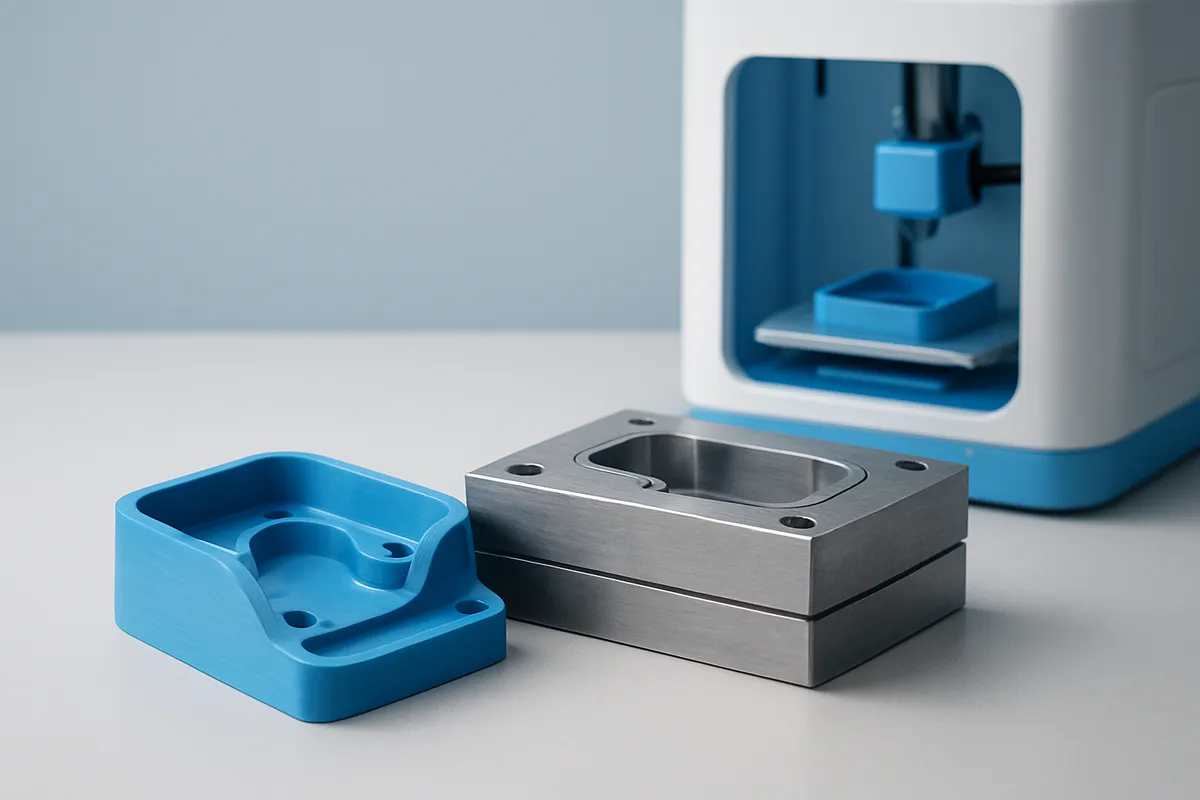
- 3D-Printed Polymer Inserts: Fastest turnaround, rated for 50–500 shots — best for fit-and-function validation before committing to metal tooling.
Rapid injection molding sits within this landscape as the downstream application: it uses rapid tooling, most often aluminum, to produce injection-molded parts on timelines that conventional tooling cannot match, bridging the gap between a finalized CAD model and confirmed production geometry.
How Rapid Tooling Manufacturing Works: Process Steps and 3D Printing’s Role
Rapid tooling manufacturing moves a part from CAD file to first molded sample in days by compressing the traditional mold-build sequence into fewer, faster steps. For a visual overview of how this process unfolds in practice, this YouTube walkthrough of rapid tooling in action provides a useful reference.
Step-by-Step: From CAD File to First Molded Part
The process begins with CAD preparation and a DFM (design for manufacturability) review. Engineers check draft angles, wall thickness uniformity, and gate placement at this stage, errors caught here cost hours to fix; errors caught after tool fabrication cost days and budget.
After DFM sign-off, the team selects the tool material, photopolymer resin, aluminum, or steel, based on the required shot count and part geometry. The tool insert is then fabricated: either CNC-machined from aluminum billet or additively built using SLA/SLS processes. Printed inserts are fitted into standard mold bases, which is what enables same-week turnaround for low-volume validation tools.
Surface finishing and fitting follow, cavity surfaces are polished or textured to the specified finish, and the insert is seated and aligned in the mold base. A mold trial then produces first-article parts, which go through dimensional inspection and material verification before the tool is released for production runs.
3D-Printed Tooling vs. CNC-Machined Aluminum Tooling: Trade-offs
Printed tooling, photopolymer or metal-sintered inserts, is faster and lower cost for runs under 100 shots, making it the right choice for fit-and-function validation. CNC-machined aluminum tooling holds tighter tolerances and supports 1,000 to 10,000+ shots depending on the resin and part geometry.
This distinction also separates rapid tooling from traditional rapid prototyping methods like SLA or FDM part printing. Prototype printing produces parts in surrogate materials that rarely match the mechanical properties of the final production resin or metal. Rapid tooling produces actual production-material parts, the same polymer or alloy specified for the finished product, which is what makes first-article data from a rapid tool genuinely predictive of production performance.
“The shift from prototype printing to rapid tooling is the moment a development program becomes real. You are no longer testing a surrogate — you are testing the actual process, material, and geometry that will go to market.” — Paul Reyes, Senior Applications Engineer, Rapid Protool
Cost and ROI of Rapid Tooling vs. Conventional Tooling Approaches
Rapid tooling sits at the budget-friendly to mid-range tier; traditional hardened-steel production tooling sits at the premium end—and the gap widens significantly below 10,000 parts.
For low-to-mid volume runs, amortizing a full production tool across a small part count rarely makes financial sense. A single long-life steel tool built for hundreds of thousands of cycles carries a premium upfront cost that only pays off at scale. Rapid tooling manufacturing shifts that equation by matching the tool investment to the actual volume required.
When Rapid Tooling Saves Money, and When It Doesn’t
The clearest ROI case is time-to-market. Conventional tooling lead times typically run 12–20 weeks; rapid tooling compresses that window to 1–4 weeks. Those recovered weeks translate directly into earlier revenue, faster design iteration, and lower carrying costs on inventory and development overhead—all measurable without a single currency figure.
Three scenarios consistently deliver positive returns:
- Bridge tooling: producing saleable parts while a full production tool is still being built.
- Market-validation runs: testing demand before committing to a premium-tier tool investment.
- Low-volume production: where a hardened-steel tool would never be fully amortized.
The honest counterpoint is total cost of ownership. Rapid tools carry shorter service lives and lower rated shot counts than hardened steel. Per-part cost rises as volumes scale beyond the tool’s design limit—because re-tooling frequency adds up. Dimensional drift over a tool’s life is also a real factor, requiring closer monitoring and more frequent maintenance cycles.
The decision rule is straightforward: if your validated volume sits above the tool’s rated shot count, the economics shift toward conventional tooling. Below that threshold, rapid tooling almost always wins on total cost.
Industries and Applications Where Rapid Tooling Delivers the Most Value
Automotive, medical devices, consumer electronics, and aerospace gain the most from rapid tooling manufacturing, each for distinct reasons tied to timeline pressure and volume.
Automotive: Validation and Bridge Production
Automotive teams use rapid tooling for interior trim validation, under-hood component testing, and bridge production during model changeovers. A weeks-long tooling gap on an active assembly line translates directly to halted production and lost revenue, bridge tooling closes that window while the production tool is still being cut.
Medical Devices: Iterating Before FDA Submission
FDA submission timelines leave little room for late-stage design changes. Rapid tooling lets development teams produce functional parts in final-grade materials, ABS, PC, and PEEK, for biocompatibility and fit testing before committing to a Class III hardened production tool. According to the U.S. Food and Drug Administration’s guidance on 3D printing and medical devices, early-stage material validation is a critical step in the regulatory pathway for implantable and functional components. A representative workflow: a medical device company uses a 3D-printed insert tool to produce 50 functional housings for clinical trials in 10 days, identifies a wall-thickness issue, revises the CAD, and re-tools in another week. That single iteration cycle avoids a costly change order on a hardened tool.
Consumer Electronics: Hitting Fixed Launch Windows
Product launch dates in consumer electronics are non-negotiable. Rapid tooling lets OEMs validate enclosure geometry, snap-fit features, and surface finish in production materials before the production tool is complete, catching fit issues that only appear in the final material, not in a prototype resin.
Aerospace and Defense: Low-Volume, High-Mix Supply
Full production tooling is rarely justified when annual volumes run in the dozens or low hundreds. Aluminum or composite rapid tooling supports small-batch part supply for aerospace and defense programs without the overhead of a full tool program, keeping certified parts available without capital-intensive tooling commitments. The Society of Manufacturing Engineers (SME) has documented how additive and rapid tooling methods are increasingly integrated into aerospace supply chains to support low-volume, high-mix production requirements.
Bridge Tooling: Keeping Production Running While the Production Tool Is Built
Bridge tooling is the most time-sensitive application across all four industries. It fills the gap between end-of-life tooling and new production tooling, a period that can run four to sixteen weeks depending on tool complexity. Aluminum bridge tools, machined to near-production tolerances, keep parts flowing to assembly lines and distribution channels without interruption.
How to Implement Rapid Tooling in Your Manufacturing Process
Start by identifying which parts in your development pipeline carry the highest design-change risk or the tightest delivery constraint. Those are the candidates for rapid tooling first. Share final STEP or IGES files with your manufacturing partner early, GC INDUS, for example, accepts orders from a single piece and machines to tolerances as tight as ±0.001mm, which means a bridge or prototype tool can be validated against production-intent specs from day one. Agree on material grade, surface finish, and shot count before tool cutting begins, and build one revision cycle into your schedule as a baseline assumption rather than a contingency.
Limitations, Tolerances, and Quality Standards in Rapid Tooling
Rapid tooling manufacturing delivers faster, lower-cost tools, but with measurable trade-offs in precision, surface finish, and shot life that engineers must plan for.
Tolerances Achievable with Rapid Tooling vs. Production Tooling
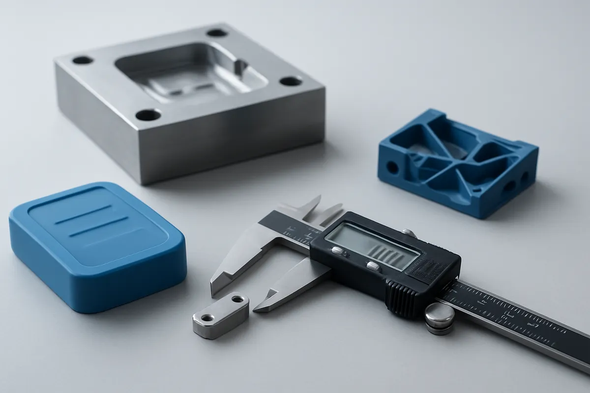
CNC-machined aluminum rapid tooling typically holds part tolerances of ±0.05–0.10 mm on most features. That’s tighter than most prototype processes, but looser than hardened P20 or H13 steel tooling, which routinely achieves ±0.01–0.025 mm on critical dimensions.
3D-printed polymer inserts perform a tier below that, generally ±0.1–0.3 mm depending on the print process and material. For optical or cosmetic parts requiring SPI A1 mirror finishes, hardened steel remains the only reliable option. Rapid tooling can achieve SPI A2–B2 finishes with post-machining and polishing, which satisfies most functional and semi-cosmetic applications.
Parts produced from rapid tools must still meet the same quality standards as those from production tooling. Aerospace programs require first-article inspection (FAI) per AS9102; automotive suppliers submit PPAP documentation; general manufacturing programs follow ISO 9001-compliant dimensional reporting standards. The tool’s origin doesn’t change the part’s acceptance criteria.
Failure Rates and Durability: What to Expect Over a Tool’s Life
Aluminum tools typically support 1,000–10,000 shots, depending on resin abrasiveness and part geometry. Glass-filled or mineral-loaded resins accelerate surface erosion and are a known cause of premature tool wear, design margins and scheduled inspection intervals reduce unplanned downtime.
3D-printed polymer inserts carry significantly shorter rated lives, often 50–500 shots. Aluminum tools also show susceptibility to galling on tight-tolerance cores and thermal fatigue on thin walls. Matching tool material to production volume at the outset prevents mid-run failures that cost more than a proper steel tool would have.
Frequently Asked Questions
What is the difference between rapid tooling and rapid prototyping?
Rapid prototyping produces a physical model of a part; rapid tooling produces the mold or die used to manufacture that part at scale. Prototyping validates geometry and fit—often using 3D printing or SLA to create a single representative piece. Rapid tooling goes one step further: it creates a functional production tool, typically from aluminum or steel, so you can run real materials through a real process and validate both the part and the manufacturing method before committing to hardened production tooling.
How many parts can a rapid tooling mold produce before it needs replacing?
Aluminum rapid tooling molds typically yield between 1,000 and 10,000 shots before wear becomes a factor. Steel bridge tools extend that range considerably—often to 100,000 parts or more—depending on the resin type, part geometry, and injection pressures involved. Abrasive or glass-filled materials shorten mold life at any tier. The right tool material depends on your target volume: aluminum for low-volume validation, steel for higher-volume bridge or production runs.
Can rapid tooling be used for production runs, or only for prototypes?
Rapid tooling can support genuine production runs, not just prototypes. Aluminum tools handle short-run production up to several thousand parts, while steel bridge tools cover mid-volume needs until full hardened tooling is ready. Many manufacturers use rapid tooling to fulfill initial market demand or cover a product launch window—then transition to hardened production tooling once volumes justify the investment.
What surface finishes are achievable with rapid tooling?
Rapid tooling molds can deliver a range of surface finishes, from matte and textured to smooth and polished, depending on how the tool cavity is finished. SPI finish standards (A1 through D3) apply to aluminum and steel rapid tools just as they do to production tooling. Texture patterns, logos, and draft-angle-dependent finishes are achievable, though very high-gloss optical finishes may require additional hand-polishing time.
How do I choose the right rapid tooling partner for my project?
When selecting a rapid tooling manufacturing partner, evaluate their material range, tolerance capabilities, and willingness to conduct a DFM review before quoting. A capable partner should accept standard CAD formats (STEP or IGES), offer aluminum and steel insert options, and provide first-article inspection reports with every tool release. Experience in your specific industry — medical, automotive, or aerospace — is also valuable, as each sector carries distinct quality documentation requirements such as PPAP or AS9102 first-article inspection.
Conclusion
Rapid tooling manufacturing closes the gap between a validated prototype and a production-ready part—without the cost or lead time of full hardened tooling. The practical takeaway: match your tool material to your volume target. Aluminum tools work for validation runs and early market supply; steel bridge tools carry you through mid-volume production until demand justifies permanent tooling investment.
Quality control at the tooling stage determines part quality downstream. Inspect your first shots rigorously—dimensional checks, material behavior, surface finish—before approving a tool for any production run.
If your next product launch requires tight-tolerance parts with a fast turnaround, request a fast quote from GC INDUS with your STEP or IGES file and specify your target volume. That single step starts the tooling conversation with real data, not estimates.
Recommended Articles
Explore more from our content library:


