Book Appointment Now


How to Master Multi-Part Assembly Manufacturing
Learn how multi-part assembly manufacturing works, from design to final inspection. Practical steps, expert tips, and quality strategies for 2026. Discover.
| Key Insight | Explanation |
|---|---|
| Design for Assembly (DfA) reduces cost | Simplifying part count and using self-mating geometry can cut assembly labor by 30–50% before a single component is machined. |
| Tolerance stack-up is the #1 failure point | Each individual part tolerance accumulates across an assembly. Tight per-part tolerances (±0.001mm) prevent misalignment and rework at the final stage. |
| Sub-assembly sequencing matters | Building in logical sub-assembly stages reduces errors, enables parallel production, and simplifies quality inspection checkpoints. |
| Single-source manufacturing reduces risk | Using one partner for machining, casting, and assembly eliminates interface errors between suppliers and speeds up delivery cycles. |
| ISO certification is non-negotiable for regulated industries | ISO 9001 and ISO 13485 certifications ensure quality management and medical device compliance throughout the entire assembly process. |
| Bill of Materials (BOM) discipline drives efficiency | A clean, accurate BOM is the foundation of every successful multi-part assembly project. Errors here cascade into production delays and cost overruns. |
Your product has 47 components. Each one needs to fit precisely with the next. One out-of-tolerance part can cascade into a full assembly failure, a delayed shipment, and an unhappy OEM client. Multi-part assembly manufacturing is the structured process of designing, producing, and joining multiple discrete components into a single functional product or sub-assembly. Done right, it delivers finished parts ready for integration. Done poorly, it creates rework loops that erode margins and damage supplier relationships.
This guide walks you through every stage of the process, from drafting your Bill of Materials to executing final quality validation. Whether you’re managing a 5-part medical device housing or a 200-component industrial mechanism, the same core principles apply. Expect to spend 20–40 minutes with this guide. The difficulty level is intermediate, assuming basic familiarity with manufacturing processes and CAD file formats.
What Is Multi-Part Assembly Manufacturing?
Multi-part assembly manufacturing is the end-to-end process of producing multiple individual components and joining them into a complete, functional product or sub-assembly. It spans design, fabrication, inspection, and joining, and it requires tight coordination between every production stage to achieve a working final product.
The term covers a wide range of complexity. A simple two-piece bracket joined by fasteners qualifies. So does a 300-component aerospace actuator assembled under cleanroom conditions. What they share is the need to manage how individual part tolerances interact across the full assembly, a concept engineers call tolerance stack-up (the cumulative dimensional variation that results when multiple parts are joined together).
Why Multi-Part Assembly Differs from Single-Part Production
Single-part production focuses on achieving a specified geometry within a defined tolerance. Multi-part assembly manufacturing adds a second layer of complexity: each component must not only meet its own spec, but also interface correctly with every adjacent part.
According to research published in the Journal of Manufacturing and Materials Processing [1], assembly design must account for geometric variation at every mating surface. A part that passes individual inspection can still cause assembly failure if its tolerance interacts unfavorably with a mating component.
Industry analysts suggest that assembly-related rework accounts for 20–30% of total manufacturing cost in complex product lines. Getting the design and process right before production starts is always cheaper than fixing it afterward.
Where Multi-Part Assembly Is Used
- Medical devices: Surgical instruments, implantable housings, diagnostic equipment
- Automotive: Transmission sub-assemblies, brake calipers, sensor housings
- Electronics: Enclosures, heat sink assemblies, connector housings
- Industrial machinery: Gearboxes, actuators, fluid control manifolds
- Aerospace: Structural brackets, hydraulic components, avionics enclosures
What You’ll Need: Prerequisites and Tools
Before starting a multi-part assembly manufacturing project, you need to have the right documentation, software, and manufacturing capabilities in place. Missing any of these at the outset will create delays and cost overruns downstream.
Documentation and Design Files
- CAD files in STEP or IGES format for every component
- Engineering drawings with GD&T (Geometric Dimensioning and Tolerancing) callouts for all critical features
- Bill of Materials (BOM) listing every part, material, quantity, and revision level
- Assembly drawing showing how components relate spatially and functionally
- Material specifications including alloy grades, hardness requirements, and surface finish standards
Manufacturing Capabilities Required
The specific processes you’ll need depend on your part geometries and materials. Most multi-part assembly projects draw on several of the following:
| Process | Typical Use Case | Achievable Tolerance |
|---|---|---|
| CNC Milling / Turning | Structural brackets, housings, shafts | ±0.001mm–±0.01mm |
| 5-Axis CNC Machining | Complex geometry, undercuts, compound angles | ±0.002mm–±0.01mm |
| Die Casting | High-volume aluminum/magnesium housings | ±0.05mm–±0.1mm |
| Injection Molding | Plastic enclosures, clips, inserts | ±0.05mm–±0.2mm |
| Sheet Metal Fabrication | Panels, brackets, enclosures | ±0.1mm–±0.3mm |
| EDM (Electrical Discharge Machining) | Hardened steel, intricate cavities | ±0.002mm–±0.005mm |
Pro Tip: Confirm that your manufacturing partner holds ISO 9001 certification as a baseline, and ISO 13485 if any component will be used in a medical device application. These certifications define the quality management system requirements that govern every step of production, not just final inspection.
Step 1: Define Your Bill of Materials (BOM)
Establish a complete, accurate Bill of Materials before any manufacturing begins. The BOM is the single source of truth for your entire multi-part assembly manufacturing project, and errors here propagate into every downstream process.
What a Solid BOM Includes
A BOM for a multi-part assembly should capture more than just part names and quantities. Each line item needs enough detail to allow procurement, production planning, and quality control to work from the same document without ambiguity.
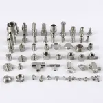
- Part number and revision level for every component
- Material specification including alloy grade (e.g., 6061-T6 aluminum, 316L stainless steel)
- Quantity per assembly
- Manufacturing process assigned to each part (CNC, casting, molding, etc.)
- Surface treatment or heat treatment requirements (e.g., anodizing, case hardening)
- Critical dimensions and tolerances flagged for inspection
- Supplier or in-house designation for each component
Protolabs notes that two core tenets of Design for Manufacturing and Assembly (DfMA) are to shrink the BOM and make products easy to assemble [2]. Before finalizing your BOM, challenge every line item. Can two parts be combined into one? Can a standard fastener replace a custom one?
BOM Management in Practice
In one project we handled for an automotive Tier-2 supplier, the initial BOM contained 34 line items. A DfMA review before production reduced that to 22 components by consolidating several bracket geometries and switching from custom pins to standard dowels. The result was a 19% reduction in per-unit assembly cost.
Use your ERP system (SAP, NetSuite, or equivalent) to manage BOM revisions. Every change must be documented with a revision number and an effectivity date. Undocumented BOM changes are a leading cause of assembly errors and quality escapes.
Pro Tip: Create a separate “critical characteristics” register alongside your BOM. List every dimension, feature, or material property that directly affects form, fit, or function in the final assembly. These are the dimensions your inspection plan must verify 100% of the time, not just on a sampling basis.
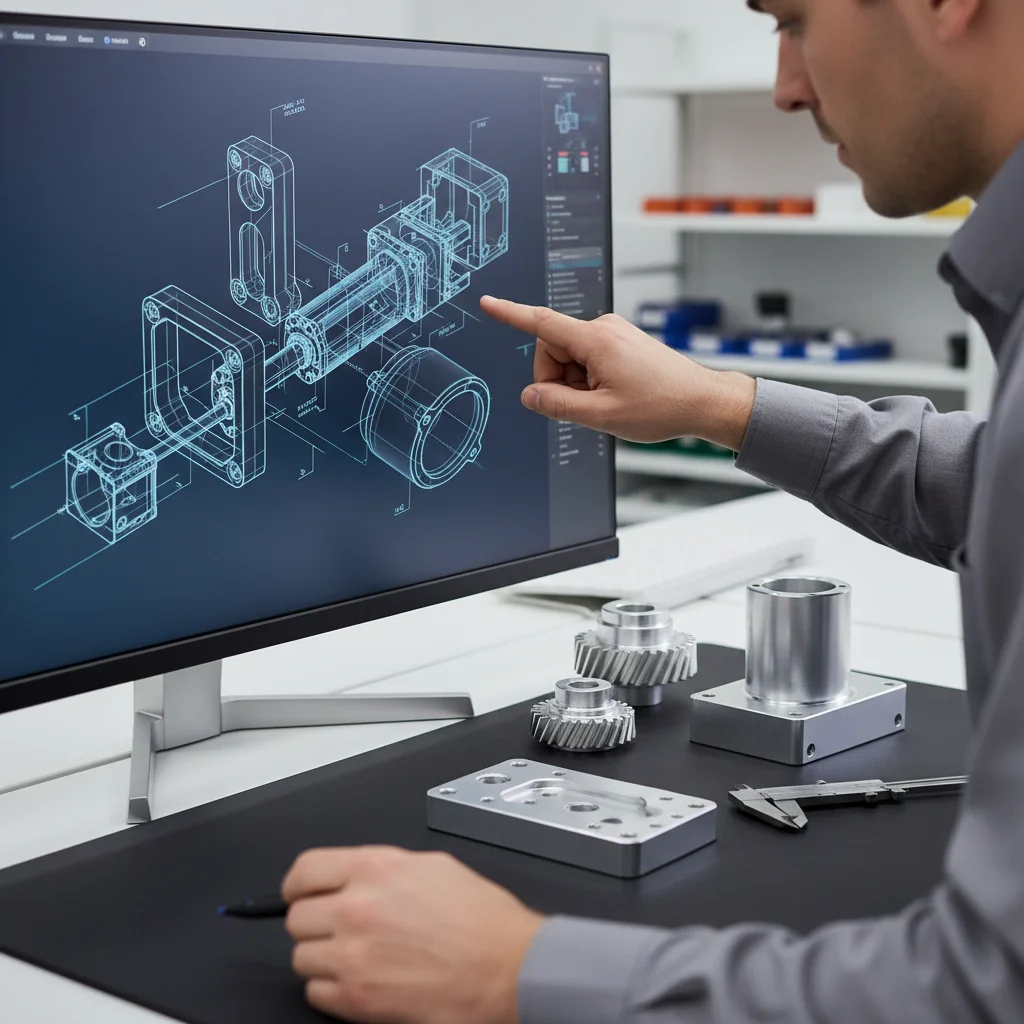
Step 2: Design for Assembly — Best Practices for 2026
Apply Design for Assembly (DfA) principles during the design phase to reduce part count, simplify joining methods, and eliminate assembly ambiguity. DfA is the most cost-effective intervention in any multi-part assembly manufacturing project because changes at the design stage cost a fraction of changes made during production.
Core DfA Strategies
The following strategies are consistently cited in engineering literature and validated in practice [3][4]:
- Reduce part count. Combine functions into single components wherever geometry and material allow. Fewer parts mean fewer assembly steps, fewer tolerance interfaces, and fewer potential failure points.
- Design self-locating features. Add datum surfaces, pins, or snap features that guide components into their correct position without requiring jigs or fixtures. This reduces assembly time and operator error.
- Use symmetrical parts. Symmetric geometry eliminates the possibility of installing a part in the wrong orientation. If symmetry isn’t possible, make asymmetry obvious with a visible feature or color coding.
- Design for top-down assembly. Where possible, design the assembly sequence so all components are inserted from above. This allows gravity to assist placement and simplifies automated assembly integration.
- Standardize fasteners. Using one or two fastener sizes across an assembly reduces tooling changes and the risk of using the wrong fastener in the wrong location.
- Design self-mating parts. Components that can only mate in one correct configuration eliminate assembly errors entirely.
Research from SUNY indicates that part decomposition and assembly-based redesign can significantly improve manufacturability when applied systematically during the design phase [5].
Tolerance Planning Across the Assembly
Tolerance stack-up analysis is not optional. For any assembly with three or more mating surfaces, run a worst-case or statistical tolerance analysis before releasing drawings for production. MIT research on automated assembly algorithms confirms that dimensional variation across multiple components is the primary driver of assembly failure in complex products [6].
Assign tighter tolerances only to features that directly affect assembly fit or function. Over-tolerancing drives up machining cost without improving product performance. Every ±0.001mm tolerance callout should be justified by a functional requirement.
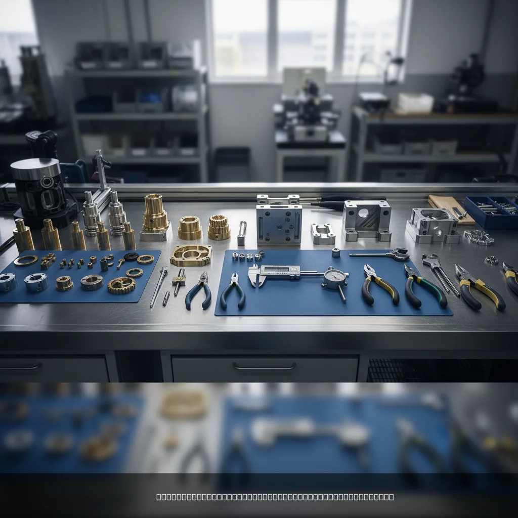
Step 3: Manufacture and Inspect Individual Components
Produce each component to its specified drawing requirements and verify conformance before it enters the assembly process. Releasing non-conforming parts into assembly is the single fastest way to generate expensive rework.
Selecting the Right Process for Each Component
Not every part in a multi-part assembly manufacturing project needs CNC machining. Match the manufacturing process to the part’s geometry, material, tolerance requirements, and volume.
- CNC milling and turning suit prismatic and rotational geometries with tight tolerances. We hold tolerances to ±0.001mm using advanced CNC machines at GC INDUS.
- 5-axis CNC machining handles complex contoured surfaces that would require multiple setups on 3-axis equipment, reducing fixturing error.
- Swiss lathe turning excels at small-diameter, high-precision parts like pins, shafts, and threaded inserts.
- Die casting suits high-volume aluminum or magnesium housings where per-unit cost matters more than extreme dimensional precision.
- Injection molding works for plastic components with moderate tolerances and high volumes.
- EDM (Electrical Discharge Machining) is the right choice for hardened materials or intricate internal geometries that cutting tools can’t reach.
Incoming and In-Process Inspection
Inspection at the component level must happen before assembly, not after. A structured inspection plan includes:
- Dimensional inspection using CMM (Coordinate Measuring Machine) or calibrated gauges for all critical characteristics
- Surface finish verification using profilometers where Ra (average roughness) values are specified
- Material certification review confirming alloy grade and mechanical properties match the BOM specification
- Visual inspection for burrs, surface defects, or machining marks that could affect mating surfaces
- Functional gauging for features like threaded holes, press-fit bores, or locating pins
A precision manufacturing client in the medical device sector recently faced a situation where 8% of incoming castings from a previous supplier had porosity defects that weren’t caught until final assembly leak testing. Catching that at the casting inspection stage would have saved three weeks of rework. Full inspection protocols at the component level are not overhead. They’re insurance.
Step 4: Plan Your Multi-Part Assembly Manufacturing Sequence
Establish the assembly sequence before production starts, defining which components are joined first, what sub-assemblies are built in parallel, and where inspection checkpoints occur. A well-planned sequence reduces assembly time, prevents access problems, and makes quality control manageable.
Building Sub-Assemblies First
Sub-assemblies are generally defined as processes involving two or more parts that form a component of a larger product assembly [7]. Breaking a complex assembly into logical sub-assemblies offers several advantages:
- Sub-assemblies can be built and tested in parallel, compressing the overall production timeline
- Defects are caught at a lower level of complexity, reducing rework cost
- Sub-assembly testing (e.g., leak test on a fluid manifold sub-assembly) confirms function before the part is buried inside a larger structure
- Parallel sub-assembly production enables better resource utilization across the shop floor
According to industry guidance from contract assembly specialists, logical sub-assembly grouping is one of the most effective ways to manage complexity in high-part-count products [8].
Defining Assembly Checkpoints
Map inspection checkpoints into the sequence at every stage where a defect would become inaccessible or expensive to correct after the next step. Typical checkpoints include:
- After each sub-assembly is completed
- Before any permanent joining operation (welding, adhesive bonding, press fitting)
- After surface treatment or heat treatment if these are applied to assembled components
- Before final enclosure or sealing, when internal features are still accessible
- At final assembly completion, before packaging
Pro Tip: Document your assembly sequence in a written Assembly Process Instruction (API). Include photos or CAD screenshots of each step. This eliminates ambiguity for assembly technicians, makes training faster, and provides a traceable record for quality audits. Under ISO 9001, documented work instructions are a requirement, not a suggestion.
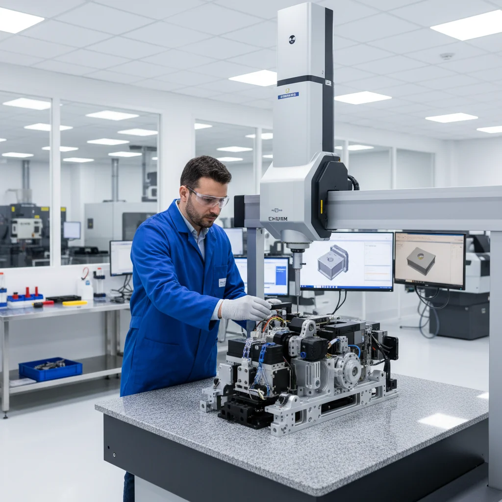
Step 5: Execute Final Assembly and Quality Validation
Complete the final assembly by joining all sub-assemblies and individual components per the documented sequence, then validate the finished product against all dimensional, functional, and cosmetic requirements. This is where multi-part assembly manufacturing either delivers or fails.
Joining Methods and Their Implications
The joining method you choose affects both the assembly process and the finished product’s performance. Common methods include:
- Threaded fasteners: Reversible, adjustable, and widely understood. Require torque specification and verification for critical joints.
- Press fitting: Delivers high holding force without fasteners. Requires precise bore and shaft tolerances (typically H7/p6 or equivalent fits) and controlled insertion force.
- Adhesive bonding: Suitable for dissimilar materials or where fasteners would compromise aesthetics. Requires surface preparation and cure time management.
- Welding / brazing: Permanent and high-strength. Introduces heat that can distort precision features, requiring post-weld machining in some cases.
- Snap fits and clips: Fast and tool-free. Best suited for plastic components where deflection force is predictable.
Final Inspection and Quality Validation
At GC INDUS, we’ve found that the most effective final inspection protocol combines dimensional verification, functional testing, and cosmetic review in a single structured pass. This avoids the inefficiency of running three separate inspection stages and ensures nothing falls through the gaps.
Final validation for a typical precision assembly includes:
- Dimensional audit of all critical assembly-level dimensions (not just individual part dimensions)
- Functional test appropriate to the product (e.g., pressure test, electrical continuity check, torque verification)
- Cosmetic inspection for surface finish, marking, and labeling requirements
- Documentation review confirming all inspection records, material certifications, and process records are complete
- First Article Inspection (FAI) for new assemblies or after any engineering change, per AS9102 or equivalent standard
Common Mistakes to Avoid
The most common failures in multi-part assembly manufacturing are predictable and preventable. Most stem from insufficient planning at the design stage or inadequate communication between design and production teams.
Design-Stage Mistakes
- Over-tolerancing every feature. Applying ±0.001mm tolerances to non-critical features drives machining cost up without improving product performance. Tolerance callouts should reflect functional requirements, not engineering conservatism.
- Ignoring tolerance stack-up. A common mistake is designing each part to a reasonable individual tolerance without analyzing how those tolerances accumulate across the assembly. The result is assemblies that pass component inspection but fail to fit together.
- Designing parts that are difficult to orient. If an assembly technician can install a component in two orientations and only one is correct, someone will eventually install it wrong. Design out ambiguity with asymmetric features or keyed interfaces.
- Not designing for disassembly. Products that require maintenance or repair need to be disassembled. Designs that don’t account for this create service problems and warranty costs.
Production and Process Mistakes
- Skipping incoming inspection. One pitfall to watch for is releasing components directly from delivery into assembly without dimensional verification. This is the most direct route to discovering tolerance problems at the worst possible moment.
- Undocumented assembly sequences. Verbal instructions don’t scale. When assembly technicians change, institutional knowledge leaves with them. Written, illustrated Assembly Process Instructions are essential.
- Using multiple suppliers without interface management. Parts from different suppliers may each conform to their individual drawings but fail to interface correctly due to differing interpretations of datum references or GD&T callouts. Single-source manufacturing or rigorous inter-supplier tolerance management prevents this.
- Skipping sub-assembly testing. Building a complete assembly before testing any sub-assemblies means that a defect found at final inspection could require disassembling the entire product to locate and fix the root cause.
- Neglecting surface treatment sequencing. Applying anodizing or plating after assembly can block threaded holes, alter fit dimensions, or create galvanic corrosion at dissimilar metal interfaces. Plan surface treatment timing carefully.
| Mistake | Stage | Prevention |
|---|---|---|
| Over-tolerancing | Design | Tolerance justified by functional requirement only |
| Ignoring stack-up | Design | Worst-case or RSS tolerance analysis before release |
| No incoming inspection | Production | 100% CMM check on critical characteristics |
| Undocumented sequence | Production | Written Assembly Process Instructions with photos |
| Multi-supplier interface errors | Procurement | Single-source manufacturing or inter-supplier tolerance review |
Sources and References
- MDPI, “Review on Additive Manufacturing of Multi-Material Parts,” 2022
- Protolabs, “How to Design for Assembly,” 2023
- Protolabs, “Tips for Designing Multipart Assemblies,” 2023
- Made In Ireland, “9 Strategies for Designing Multipart Assemblies,” 2023
- SUNY Research Connect, “Part Decomposition and Assembly-Based (Re)Design for Additive Manufacturing,” 2021
- MIT News, “An Automated Way to Assemble Thousands of Objects,” 2022
- MSI, “The Insider’s Guide to Contract Assembly and Sub-Assembly for Manufacturers,” 2023
- EZG Manufacturing, “What Are Contract Assembly Services?,” 2023
- PMC / NIH, “A Multi-Part Orientation Planning Schema for Fabrication of Non-Planar Parts,” 2022
- Universal Plastic Mold, “Multipart Assemblies,” 2023
Frequently Asked Questions
1. What is multi-part assembly manufacturing?
Multi-part assembly manufacturing is the process of producing multiple individual components through machining, casting, molding, or fabrication, then joining them into a single functional product or sub-assembly. It requires coordinated design, production, inspection, and joining processes to ensure all components fit and function correctly together. It’s used across automotive, medical, aerospace, and industrial sectors.
2. What is tolerance stack-up and why does it matter in assembly?
Tolerance stack-up refers to the cumulative dimensional variation that results when multiple parts are joined together. Each individual part has its own dimensional tolerance, and when those tolerances combine across an assembly, the total variation can exceed the functional limit even if every individual part passes inspection. Worst-case and RSS (Root Sum Square) analysis methods are used to predict and control stack-up before production begins.
3. What is Design for Assembly (DfA)?
Design for Assembly (DfA) is a methodology that guides engineers to design products with assembly efficiency in mind. Core DfA principles include reducing part count, using self-locating features, designing symmetric or obviously asymmetric parts, standardizing fasteners, and enabling top-down assembly. Applied during the design phase, DfA can reduce assembly labor cost by 30–50% and significantly lower the risk of assembly errors.
4. What is a sub-assembly in manufacturing?
A sub-assembly is a group of two or more components that are joined together as a unit before being integrated into a larger final assembly. Sub-assemblies can be built and tested independently, which enables parallel production, simplifies quality inspection, and reduces the cost of fixing defects. Common examples include a gearbox housing with bearings pressed in, or a manifold block with fittings installed.
5. How do I choose between ordering individual components vs. a completed assembly?
Ordering a completed assembly from a single manufacturer typically reduces total cost of ownership compared to sourcing individual components from multiple suppliers and assembling in-house. A single-source assembly partner eliminates interface errors between suppliers, reduces logistics complexity, and provides a single point of accountability for quality. The trade-off is less control over individual component sourcing. For most OEM applications, completed assembly sourcing is more cost-effective at volumes above a few hundred units per year.
6. What certifications should a multi-part assembly manufacturing partner hold?
At minimum, look for ISO 9001 certification, which confirms a documented quality management system covering design, production, inspection, and continuous improvement. For medical device components, ISO 13485 is required, as it adds device-specific requirements for traceability, risk management, and sterile packaging processes. For aerospace applications, AS9100 certification is the relevant standard. As of 2026, these certifications remain the primary quality baseline for global OEM procurement decisions.
7. What is a First Article Inspection (FAI) and when is it required?
A First Article Inspection (FAI) is a comprehensive dimensional and functional verification of the first production part or assembly produced from a new manufacturing process or after a significant engineering change. FAI confirms that the manufacturing process is capable of producing parts that conform to all drawing requirements. It’s required by most aerospace and defense customers per AS9102, and strongly recommended for any precision assembly entering volume production for the first time.
8. Can multi-part assembly manufacturing be done with a minimum order of 1 piece?
Yes. Some precision contract manufacturers, including GC INDUS, accept orders from a single piece, which is particularly valuable for prototyping and low-volume production. This eliminates the minimum order quantity (MOQ) barriers that force companies to over-order and carry excess inventory. Prototype assemblies allow design validation before committing to volume production tooling, reducing overall development risk and cost.
Conclusion
Multi-part assembly manufacturing is not a single process. It’s a coordinated system spanning design, material selection, component production, inspection, and joining. Get the design right with DfA principles, build a clean BOM, inspect every component before it enters the assembly, plan your sequence with sub-assembly logic, and validate the finished product against functional requirements.
The steps covered in this guide are:
- Define a complete and accurate Bill of Materials
- Apply Design for Assembly principles to reduce part count and eliminate ambiguity
- Manufacture and inspect individual components before assembly
- Plan the assembly sequence with sub-assembly stages and inspection checkpoints
- Execute final assembly and validate against dimensional, functional, and cosmetic requirements
Results will vary depending on product complexity, material selection, and the capabilities of your manufacturing partner. One limitation this guide doesn’t cover in depth is automated assembly, which introduces additional considerations around fixturing, vision systems, and robot programming.
Our team at GC INDUS recommends treating assembly as a design problem, not just a production problem. The decisions made during design determine 70–80% of assembly cost and quality outcomes. If you’re sourcing a multi-part assembly and want a partner who holds ±0.001mm tolerances, carries ISO 9001 and ISO 13485 certifications, and handles everything from CNC machining to final assembly inspection under one roof, GC INDUS works with 300+ global clients across exactly these requirements.
Recommended Articles
Explore more from our content library: