Book Appointment Now


CMM Inspection: How to Achieve Dimensional Accuracy
Learn how CMM inspection dimensional accuracy works, what tolerances to expect, and how precision manufacturers use CMMs to deliver zero-defect parts.
| Key Insight | Explanation |
|---|---|
| CMM accuracy range | Standard CMMs achieve ±1 to ±5 µm; ultra-precision systems reach sub-micron levels, enabling verification of tolerances as tight as ±0.001mm. |
| Two key accuracy metrics | Volumetric Length Measuring Uncertainty (E) and Probing Uncertainty (R) are the primary indicators used to evaluate CMM performance per ISO 10360. |
| Environmental impact | Temperature, vibration, and humidity all affect measurement results. Controlled lab conditions at 20°C (68°F) are the ISO standard for CMM operation. |
| GD&T integration | Modern CMMs evaluate GD&T (Geometric Dimensioning and Tolerancing) features including flatness, perpendicularity, runout, and true position against CAD models. |
| CMM types compared | Bridge, gantry, and articulating arm CMMs each suit different part sizes and precision requirements; scanning probes outperform touch-trigger probes for complex geometries. |
| Certification alignment | ISO 9001 and ISO 13485 certified manufacturers rely on CMM inspection as a core quality control checkpoint to meet regulatory and client requirements. |
Your OEM client just flagged a batch of machined housings. The dimensions look right to the naked eye, but three parts failed assembly. The root cause? No CMM verification in the inspection chain. CMM inspection dimensional accuracy is the process of using a Coordinate Measuring Machine (CMM) to verify that a manufactured part’s physical geometry matches its design specifications within defined tolerance limits. It combines high-resolution probing technology with software analysis to catch deviations that manual gauges simply can’t detect. This article covers how CMMs work, what accuracy levels you can realistically expect, common pitfalls that compromise results, and the best practices that precision manufacturers follow to deliver zero-defect parts consistently.
What Is CMM Inspection Dimensional Accuracy?
CMM inspection dimensional accuracy is the measurable degree to which a Coordinate Measuring Machine’s reported values match the true physical dimensions of a part, evaluated against design tolerances and verified through standardized testing protocols such as ISO 10360.
Defining the Core Concepts
A Coordinate Measuring Machine (CMM) is a precision instrument that measures the geometry of a physical object by sensing discrete points on its surface using a probe. The machine operates in three-dimensional space (X, Y, Z axes), capturing point coordinates and computing dimensions, angles, profiles, and geometric relationships. According to Wikipedia’s entry on coordinate-measuring machines [1], CMMs are used extensively in manufacturing and assembly processes to verify that parts conform to design specifications. This is particularly relevant for CMM inspection dimensional accuracy.
Dimensional accuracy, in this context, refers to how closely those measured values align with the nominal (intended) dimensions defined in the part drawing or CAD model. It isn’t just about being “close enough.” In precision manufacturing, even a deviation of a few micrometers can cause assembly failures, functional issues, or regulatory non-compliance in sectors like medical devices or aerospace.
Two primary metrics define CMM accuracy [2]:
- Volumetric Length Measuring Uncertainty (E): How accurately the CMM measures a known length across its full work volume.
- Probing Uncertainty (R): The repeatability and accuracy of the probe when contacting a reference sphere at multiple points.
Why Dimensional Accuracy Matters in Manufacturing
Parts that fall outside tolerance don’t just fail inspection. They cause downstream problems: assembly line stoppages, field failures, warranty claims, and in regulated industries, potential safety incidents. Research published on PubMed Central [3] confirms that CMM inspection preserves dimensional accuracy through high-resolution scanning and automated compensation algorithms, even in challenging production environments.
Standard bridge CMMs achieve measurement uncertainty in the range of ±1 to ±5 µm. Ultra-precision CMMs used in optics and semiconductor manufacturing can reach sub-micron accuracy. For context, a human hair is roughly 70 µm in diameter. A ±1 µm measurement is 70 times finer than that.
| CMM Type | Typical Accuracy | Best Application | Part Size Range |
|---|---|---|---|
| Bridge CMM | ±1 to ±3 µm | General precision parts, CNC machined components | Small to medium |
| Gantry CMM | ±3 to ±10 µm | Large automotive/aerospace structures | Large to very large |
| Articulating Arm CMM | ±15 to ±50 µm | Shop-floor inspection, large or awkward parts | Medium to large |
| Ultra-Precision CMM | Sub-micron (<1 µm) | Optics, semiconductor, micro-machined parts | Small to micro |
| Portable Handheld CMM | ±50 to ±130 µm | Field inspection, on-site verification | Variable |
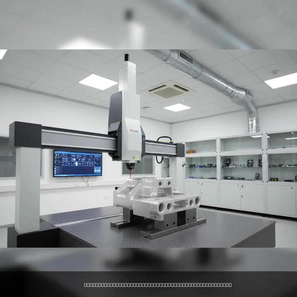
How CMM Inspection Works
A CMM measures a part by moving a calibrated probe across its surface in three-dimensional space, recording coordinate data that software then compares against the nominal CAD geometry to calculate deviations and determine pass/fail status.
The Measurement Process Step by Step
Understanding the mechanics helps you specify inspection correctly and interpret reports accurately. Here’s how a typical CMM inspection run proceeds [4]: When considering CMM inspection dimensional accuracy, this point stands out.
- Part setup and fixturing: The part is secured on the CMM table using a fixture or magnetic clamp. Proper fixturing prevents movement during measurement, which would introduce false readings.
- Probe qualification: The probe tip is calibrated against a precision reference sphere (usually ruby or ceramic) to establish its exact diameter and position offset.
- Coordinate system alignment: A datum reference frame (DRF) is established by probing reference surfaces, holes, or features that match the part drawing’s datum scheme.
- Measurement program execution: The CMM runs a pre-written measurement program (typically in DMIS or proprietary software language) that directs the probe to each feature of interest.
- Data collection: The probe contacts the part surface at defined points, recording X, Y, Z coordinates for each contact. Scanning probes capture continuous point clouds.
- Software analysis: The CMM software fits geometric elements (planes, circles, cylinders, cones) to the point data and calculates dimensions, form errors, and GD&T values.
- Report generation: Results are compared to nominal values and tolerances. The report flags any out-of-tolerance features with actual deviation values.
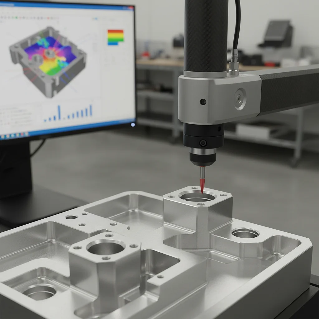
Probe Types and Their Impact on Accuracy
The probe is the most critical hardware element in the measurement chain. KEYENCE’s CMM resource [5] notes that modern CMMs can evaluate GD&T features like flatness, squareness, and parallelism with either contact or non-contact probing methods.
- Touch-trigger probes: Contact the surface at discrete points. Fast and reliable for simple prismatic features. Accuracy is limited by probe lobing (directional variation in trigger force).
- Scanning probes (analog): Maintain continuous contact and collect dense point data. Better for curved surfaces, freeform geometries, and complex profiles. Generally more accurate than touch-trigger for these features.
- Non-contact optical probes: Use laser triangulation or white-light interferometry. Ideal for soft, delicate, or highly reflective surfaces. As noted in the Wikipedia CMM article [1], scanning CMMs are often more accurate than touch-probe methods for complex geometries.
- Multi-sensor systems: Combine contact and optical probing on a single machine, allowing one setup to handle diverse feature types without re-fixturing.
Pro Tip: Always match your probe type to the part geometry. Using a touch-trigger probe on a freeform surface with tight profile tolerances will produce sparse, potentially misleading data. A scanning probe collects 10 to 100 times more points on the same feature, giving you a statistically robust result.
According to research from NJIT’s digital commons [6], every measuring device used in metrology has a defined degree of measuring accuracy, and CMMs are no exception. The key is understanding where that accuracy comes from and how to preserve it through proper operation.
Key Benefits of CMM Inspection for Dimensional Accuracy
CMM inspection dimensional accuracy delivers measurable advantages over manual gauging: faster throughput, objective data, full GD&T capability, and a documented audit trail that satisfies quality management systems like ISO 9001 and ISO 13485.
Practical Advantages Over Traditional Gauging
Manual measurement tools like calipers, micrometers, and height gauges are fast and inexpensive. But they have hard limits. They measure one feature at a time, require skilled operators, and can’t directly evaluate GD&T relationships like true position or profile of a surface. CMMs solve all three problems simultaneously.
- Comprehensive feature coverage: A single CMM program can measure hundreds of features in one setup, including dimensions, angles, radii, and GD&T callouts.
- Objective, repeatable results: CMM measurements don’t vary based on operator technique. The same program run on the same part produces consistent results, which is critical for statistical process control (SPC).
- CAD comparison: Modern CMM software imports STEP or IGES files and compares measured data directly to the 3D model, flagging deviations visually on a color map. Nel Pretech’s quality control resource [7] highlights this CAD integration as a core advantage for superior quality control.
- GD&T evaluation: CMMs calculate geometric tolerances including flatness, cylindricity, perpendicularity, runout, and true position — values that are impossible to measure accurately with hand tools.
- Documentation and traceability: Every measurement is recorded with timestamps, operator IDs, and calibration status, creating a complete quality record for audits and customer submissions.
Industry-Specific Value
Different industries rely on CMM inspection for different reasons, but the underlying need is the same: verified dimensional accuracy before parts reach the next stage of production or delivery.
- Medical devices: ISO 13485 requires documented inspection at critical stages. CMM reports serve as objective evidence that components meet specification before assembly into life-critical devices.
- Automotive: 3ERP’s CMM inspection guide [8] notes that automotive CMM inspection focuses on dimensional accuracy of components critical for assembly line efficiency and vehicle performance.
- Aerospace: AS9100 certified facilities use CMM data to support first article inspection reports (FAIRs) and ongoing production verification.
- Electronics: Miniaturized components with sub-millimeter features require CMM verification to confirm that connectors, housings, and heat sinks will assemble correctly.
At GC INDUS, we’ve found that customers who receive CMM inspection reports with their parts have significantly fewer assembly issues and return requests. The data gives engineers confidence to proceed without secondary verification on their end, which shortens their time-to-production.
Common Challenges and Mistakes in CMM Inspection
The most common CMM inspection failures aren’t equipment failures. They’re procedural: poor fixturing, ignoring thermal effects, misaligned datums, and using the wrong probe for the feature being measured. For those exploring CMM inspection dimensional accuracy, this matters.
Environmental and Setup Errors
Temperature is the single biggest environmental threat to CMM accuracy. Most materials expand and contract with temperature changes. The ISO standard for CMM measurement is 20°C (68°F). Deviating from this temperature by just 1°C can introduce errors of several micrometers on a 300mm part, depending on the material’s coefficient of thermal expansion.
FD Hurka’s analysis of environmental conditions [9] confirms that CMM precision does not exist in isolation. Vibration from nearby machinery, air currents from HVAC systems, and humidity fluctuations all affect results. A CMM placed next to a grinding machine on the shop floor will produce less reliable data than one in a dedicated, climate-controlled metrology room.
Common setup mistakes include:
- Measuring parts immediately after machining, before they’ve thermally stabilized to room temperature.
- Using inadequate fixtures that allow micro-movement during probing.
- Failing to re-qualify the probe after a collision or stylus change.
- Setting up datums that don’t match the drawing’s datum reference frame, making all subsequent measurements meaningless.
Programming and Interpretation Errors
A CMM is only as accurate as its measurement program. Poorly written programs introduce systematic errors that repeat across every part in a batch, potentially releasing an entire production run of out-of-tolerance components.
- Insufficient sample points: Measuring a bore with only 3 points can’t detect lobing or ovality. Industry practice recommends a minimum of 7 to 9 points for circular features, more for critical applications.
- Incorrect geometric fitting algorithms: Using a least-squares fit where the drawing calls for a maximum inscribed circle (or vice versa) produces results that don’t reflect the functional requirement.
- Misapplied GD&T: GD&T (Geometric Dimensioning and Tolerancing) is a standardized language defined in ASME Y14.5. Misinterpreting a composite position tolerance or a datum modifier in the CMM program leads to incorrect pass/fail decisions.
- Overlooking measurement uncertainty: Reporting a result of 9.998mm without acknowledging a measurement uncertainty of ±0.003mm is misleading. Results near the tolerance boundary require uncertainty analysis before a conformance decision is made.
Pro Tip: Always include measurement uncertainty in your CMM reports when results fall within 25% of the tolerance boundary. This practice aligns with the ASME B89.7.3.1 decision rule standard and protects both the manufacturer and the customer from false accept/reject decisions.
In practice, a common mistake we see from manufacturers new to CMM inspection is treating the CMM report as the final word without validating that the measurement program actually reflects the drawing intent. A quick review of the datum scheme and feature control frames before running the first part saves significant rework later.
Best Practices for CMM Inspection Dimensional Accuracy in 2026
As of 2026, best-in-class CMM inspection combines rigorous environmental controls, validated measurement programs, statistical process control integration, and regular machine calibration traceable to national measurement standards. This directly impacts CMM inspection dimensional accuracy outcomes.
Building a Reliable Inspection Process
Reliable CMM results start before the machine is turned on. The inspection process should be designed alongside the manufacturing process, not added as an afterthought at the end of the production line.
- Define the inspection plan early: Identify critical-to-function (CTF) dimensions during design review. These get full CMM verification; non-critical features can use faster manual gauging.
- Maintain a controlled environment: Keep CMM rooms at 20°C ±1°C with humidity between 40% and 60% RH. Allow machined parts at least 4 hours of soak time before measuring.
- Calibrate regularly and traceably: CMM calibration should be traceable to national metrology institutes (NIST in the US, PTB in Germany, NPL in the UK). Calibration intervals depend on usage intensity, typically every 6 to 12 months.
- Validate measurement programs: Run the program on a known reference artifact before using it on production parts. Document the validation results.
- Integrate SPC data: Feed CMM results into statistical process control (SPC) software to track trends. A dimension drifting toward its tolerance limit is a warning sign that can trigger corrective action before parts go out of spec.
- Use GD&T correctly: Align CMM programs strictly with ASME Y14.5 or ISO 1101 GD&T standards, depending on which standard the drawing references.
Leveraging Modern CMM Software and Automation
CMM software has advanced considerably in recent years (2024-2026). Modern platforms like PC-DMIS, CALYPSO, and Rational-DMIS now offer direct CAD import, automated measurement planning, and real-time SPC dashboards.
- Automated measurement planning: Some software can generate a measurement program automatically from a CAD model with GD&T annotations (PMI data), reducing programming time by 60-80% on complex parts.
- Color deviation maps: Visual comparison of measured surface vs. nominal CAD geometry helps engineers immediately identify problem areas without reading rows of numbers.
- Closed-loop feedback: Linking CMM output directly to CNC machine offsets allows automatic compensation for dimensional drift without human intervention.
Pro Tip: If you’re specifying CMM inspection for outsourced parts, ask your supplier to provide the full CMM report in a standard format (PDF with feature-by-feature results, not just a pass/fail stamp). This gives your engineering team actual deviation values, which are far more useful for process improvement than a simple conformance declaration.
Our team at GC INDUS recommends that clients provide STEP files with embedded PMI (Product and Manufacturing Information) data whenever possible. This allows our CMM software to extract nominal dimensions and tolerances directly from the model, reducing the risk of transcription errors and accelerating first-article inspection turnaround.
Research from a 2024 study on thin-walled milled part accuracy [10] underscores that the choice of inspection method significantly affects how accurately dimensional deviations are detected, particularly for flexible or complex geometries where part deflection under probe force can introduce measurement artifacts.

Sources & References
- Wikipedia, “Coordinate-measuring machine,” 2026
- PMT3D, “Understanding the Accuracy of Coordinate Measuring Machines,” 2026
- PubMed Central / NCBI, “Dimensional Accuracy and Measurement Variability in CNC-Turned Parts,” 2026
- Neway Aerotech, “What Is Coordinate Measuring Machine (CMM) Checking?” 2026
- KEYENCE America, “CMM in Manufacturing & Fabrication,” 2026
- NJIT Digital Commons, “Coordinate Measuring Machines: A Modern Inspection Tool in Manufacturing,” 2026
- Nel Pretech, “CMM Inspection Services For Precision Quality Control,” 2026
- 3ERP, “CMM Inspection: Basics, Capabilities and Applications,” 2026
- FD Hurka, “How Environmental Conditions Impact CMM Accuracy,” 2026
- NASA ADS / ADSABS, “Evaluation of the Dimensional Accuracy of a Milled Thin-Walled Part,” 2024
- Two Trees 3D, “What Is Advanced CMM Inspection for Dimensional Accuracy?” 2026
- Calibration Laboratory LLC, “Dimensional Inspection,” 2026
Frequently Asked Questions
1. What is CMM dimensional accuracy?
CMM inspection dimensional accuracy measures how closely a Coordinate Measuring Machine’s reported values match the true physical dimensions of a part, evaluated against design tolerances. It’s quantified through two primary indicators: Volumetric Length Measuring Uncertainty (E), which reflects accuracy across the full measurement volume, and Probing Uncertainty (R), which reflects the repeatability and precision of individual probe contacts. Together, these metrics define whether a CMM is fit for verifying a given tolerance. A CMM with E = 1.7 + 3L/1000 µm, for example, is highly capable for most precision machined parts but may be insufficient for sub-micron optics work.
2. What is meant by dimensional accuracy?
Dimensional accuracy refers to how closely a manufactured part’s physical dimensions conform to the nominal values specified in its engineering drawing or CAD model, within defined tolerance limits. It’s not a single number but a relationship between the actual measured value, the nominal target, and the allowable deviation (tolerance). High dimensional accuracy means the part will function as intended, assemble correctly with mating components, and meet regulatory requirements. Poor dimensional accuracy causes assembly failures, performance degradation, increased scrap rates, and in critical applications like medical devices or aerospace, potential safety consequences. CMM inspection is the most reliable method for objectively quantifying dimensional accuracy across complex, multi-feature parts.
3. How do you calculate the accuracy of a CMM?
CMM accuracy is evaluated per ISO 10360, the international standard for acceptance testing of coordinate measuring machines. The test involves measuring a calibrated reference artifact (typically a step gauge or ball bar) at multiple positions and orientations throughout the CMM’s working volume. For length measurement accuracy, a minimum of 35 sets of three repeated measurements are taken at different lengths and orientations. The range (maximum minus minimum) of each set of three is calculated; if all 35 values fall within the manufacturer’s specified limit (E), the CMM passes. Probing uncertainty (R) is evaluated separately by probing a reference sphere at 25 points and calculating the range of radial deviations. Both tests must pass for the CMM to be considered in specification. Calibration should be performed by an accredited metrology laboratory with traceability to national standards. This is particularly relevant for CMM inspection dimensional accuracy.
4. How accurate is a CMM?
CMM accuracy varies significantly by machine type, size, and environment. Standard bridge CMMs used in precision manufacturing achieve volumetric accuracy in the range of ±1 to ±5 µm under controlled conditions. Larger gantry CMMs for automotive and aerospace structures typically achieve ±3 to ±10 µm. Portable articulating arm CMMs are less accurate, typically ±15 to ±50 µm, but offer flexibility for large or on-site inspections. Ultra-precision CMMs used for optics, semiconductor wafers, and micro-machined parts can achieve sub-micron accuracy below 0.5 µm. The Calibration Laboratory LLC reports a maximum permissible error of E0,MPE = (1.7 + 3L/1000) µm for their high-accuracy CMM, which is representative of a capable precision inspection facility. Actual achieved accuracy depends heavily on environmental conditions, calibration status, fixturing quality, and operator competence.
5. What industries rely most on CMM inspection?
Aerospace, automotive, medical devices, and electronics manufacturing are the heaviest users of CMM inspection. Aerospace relies on CMMs for first article inspection reports (FAIRs) per AS9102 and ongoing production verification to AS9100 standards. Medical device manufacturers use CMMs to satisfy ISO 13485 documentation requirements and FDA quality system regulation (21 CFR Part 820). Automotive Tier-1 suppliers use CMMs to meet IATF 16949 quality management requirements and to feed SPC data into continuous improvement programs. Electronics manufacturers use CMMs to verify miniaturized connectors, housings, and heat sinks where sub-millimeter tolerances are common. Any industry where parts must assemble reliably, function under stress, or meet regulatory requirements benefits from CMM inspection.
6. How does temperature affect CMM accuracy?
Temperature is the dominant environmental factor affecting CMM accuracy. The ISO standard reference temperature for dimensional measurement is 20°C (68°F). Both the part being measured and the CMM structure expand or contract with temperature changes according to their respective coefficients of thermal expansion (CTE). Aluminum, for example, expands at roughly 23 µm/m/°C. A 300mm aluminum part measured at 22°C instead of 20°C will be approximately 13.8 µm longer than its true 20°C dimension, which could push a marginally conforming part into a fail decision. Climate-controlled metrology rooms, adequate thermal soak time for parts, and software-based thermal compensation are the standard mitigations. FD Hurka’s environmental impact analysis provides a thorough breakdown of all environmental variables and their relative impact on CMM results.
Conclusion
CMM inspection dimensional accuracy isn’t optional for manufacturers competing on precision. It’s the objective foundation that separates parts that work from parts that fail, and suppliers that are trusted from those that aren’t. From understanding the difference between touch-trigger and scanning probes to managing thermal effects and writing programs that correctly reflect GD&T intent, every detail in the inspection process affects the reliability of the result.
The best CMM programs are built alongside the manufacturing process, not bolted on at the end. They use calibrated equipment, controlled environments, and measurement programs validated against known reference artifacts. They feed data into SPC systems that catch drift before it becomes scrap. And they produce reports that give customers real deviation values, not just a pass stamp.
GC INDUS holds tolerances to ±0.001mm across CNC milling, turning, 5-axis machining, Swiss lathe, EDM, and die casting processes. Our full inspection protocols, backed by ISO 9001 and ISO 13485 certifications, include CMM verification for critical features on every qualified part. If your application demands documented dimensional accuracy with zero surprises at assembly, our team is ready to support you from first article through full production.
Recommended Articles
Explore more from our content library: