Book Appointment Now


Tight Tolerances in Manufacturing: A Complete Guide
Master tight tolerances manufacturing with our 2026 guide. Learn definitions, processes, benefits, and expert tips to achieve ±0.001mm precision parts.
| Key Insight | Explanation |
|---|---|
| What “tight tolerance” means | Any dimensional requirement tighter than ±0.13 mm (±0.005″) is generally considered tight; extreme precision reaches ±0.001 mm or better. |
| Industries that depend on it | Medical devices, aerospace, automotive, and electronics all require tight tolerances to guarantee safety, fit, and function. |
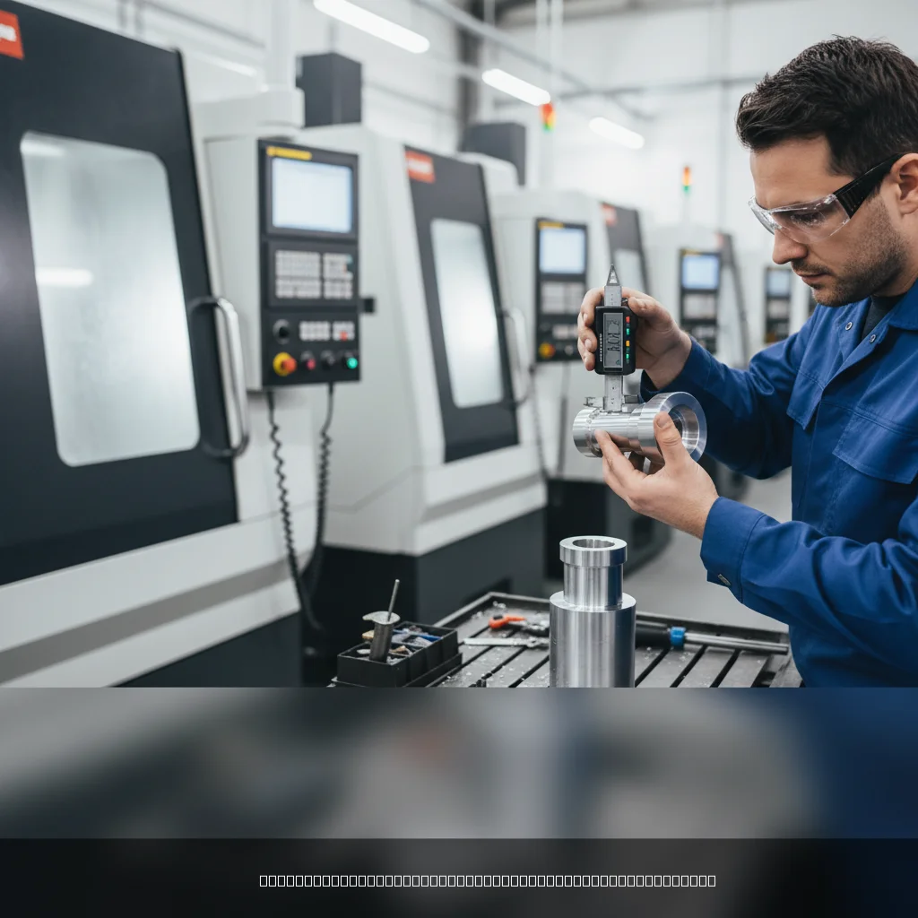
| Primary enabling technology | 5-axis CNC machining, Swiss lathe turning, EDM, and coordinate measuring machines (CMMs) are the core tools for achieving sub-micron accuracy. |
| Cost vs. precision trade-off | Tighter tolerances increase machining time, tooling cost, and scrap rate — so specifying only the tolerance you actually need is critical. |
| Relevant standards | ISO 2768 defines standard tolerance grades; ISO 9001 and ISO 13485 govern quality management for general and medical manufacturing. |
| Tolerance stackup risk | Cumulative dimensional variation across multiple parts can cause assembly failures — careful tolerance analysis prevents this outcome. |
Your OEM client just sent over a drawing with a ±0.002 mm positional callout. Your current supplier says that’s “borderline impossible.” It isn’t — but it does require a very different approach to tight tolerances manufacturing than standard job-shop work. Tight tolerances manufacturing is the practice of producing components where dimensional variation is controlled to extremely narrow limits, typically below ±0.13 mm, and often reaching ±0.001 mm or tighter in precision-critical applications. It matters because a single out-of-spec dimension can cause assembly failures, regulatory rejections, or safety incidents in fields like medical devices and aerospace. This guide covers what tight tolerances actually mean, how manufacturers achieve them, the real costs and benefits involved, and the expert practices that separate reliable precision suppliers from the rest.
What Is Tight Tolerances Manufacturing?
Tight tolerances manufacturing is the production of parts where allowable dimensional deviation is controlled to limits far stricter than general-purpose machining, typically below ±0.13 mm (±0.005″) and extending to ±0.001 mm for the most demanding applications.
Defining the Tolerance Threshold
Engineering tolerance, as defined by established standards, is the permissible limit of variation in a physical dimension [1]. Not every dimension on a part needs to be tight. Standard machining tolerances under ISO 2768 grade “m” (medium) allow deviations of ±0.1 mm to ±0.3 mm depending on the nominal size [2]. A dimension becomes “tight” when it drops below ±0.13 mm — the point where standard tooling, fixturing, and process controls are no longer sufficient on their own.
Here’s a practical breakdown of tolerance ranges you’ll encounter:
| Tolerance Range | Classification | Typical Application |
|---|---|---|
| ±0.5 mm and above | Coarse / Standard | Sheet metal brackets, structural frames |
| ±0.13 mm to ±0.5 mm | Medium precision | General mechanical assemblies |
| ±0.025 mm to ±0.13 mm | Tight | Automotive engine components, electronics housings |
| ±0.001 mm to ±0.025 mm | High precision | Medical implants, aerospace actuators, optical mounts |
| Below ±0.001 mm | Ultra-precision | Semiconductor wafer stages, laser optics |
Why Tolerances Matter Across Industries
Tight tolerances aren’t just an engineering preference — they’re often a regulatory requirement. Medical device components, for instance, must meet dimensional specifications that directly affect patient safety [3]. Aerospace assemblies depend on tight fits to prevent fatigue failures under cyclic loading. According to NASA’s Lessons Learned database, excessively tight tolerances can actually increase scrap rates and cost, while tolerances that are too loose cause integration failures [4]. The key is specifying exactly what the application demands — no tighter, no looser.
Industry analysts note that the global precision manufacturing sector continues to expand in 2026, driven by medical device reshoring, automotive electrification, and electronics miniaturization. Each of these trends pushes dimensional requirements tighter, making the ability to hold sub-0.01 mm tolerances a genuine competitive differentiator for manufacturers.
Pro Tip: Before specifying a tolerance, ask: “What is the functional consequence of this dimension being off by X?” If the answer is “nothing critical,” you don’t need a tight tolerance there. Over-tolerancing drives up cost without improving performance.
How Tight Tolerances Manufacturing Works
Achieving tight tolerances manufacturing requires a controlled system — the right machine, the right tooling, the right environment, and a measurement process that can verify what the cutting tool actually produced.
The Machining Processes That Enable Precision
Not every machining process can hold tight tolerances. The choice of process is the first decision a precision manufacturer makes. Here are the primary methods used in tight tolerances manufacturing [5]:
- 5-axis CNC milling: Machines the workpiece from five directions in a single setup, reducing repositioning errors that accumulate when you move a part between fixtures.
- CNC turning and Swiss lathe: Swiss-type lathes support the workpiece close to the cutting zone, dramatically reducing deflection on long, slender parts. Tolerances of ±0.002 mm are routinely achievable.
- EDM (Electrical Discharge Machining): Removes material via controlled electrical sparks rather than cutting force. Because there’s no mechanical contact, EDM can hold tolerances that conventional milling cannot, particularly in hardened steels.
- Grinding: Surface and cylindrical grinding are the final step for the tightest fits. A well-maintained cylindrical grinder can hold roundness within 0.001 mm.
- Wire cutting (wire EDM): Cuts complex 2D profiles through conductive materials with sub-micron positioning accuracy, ideal for dies, molds, and intricate profiles.
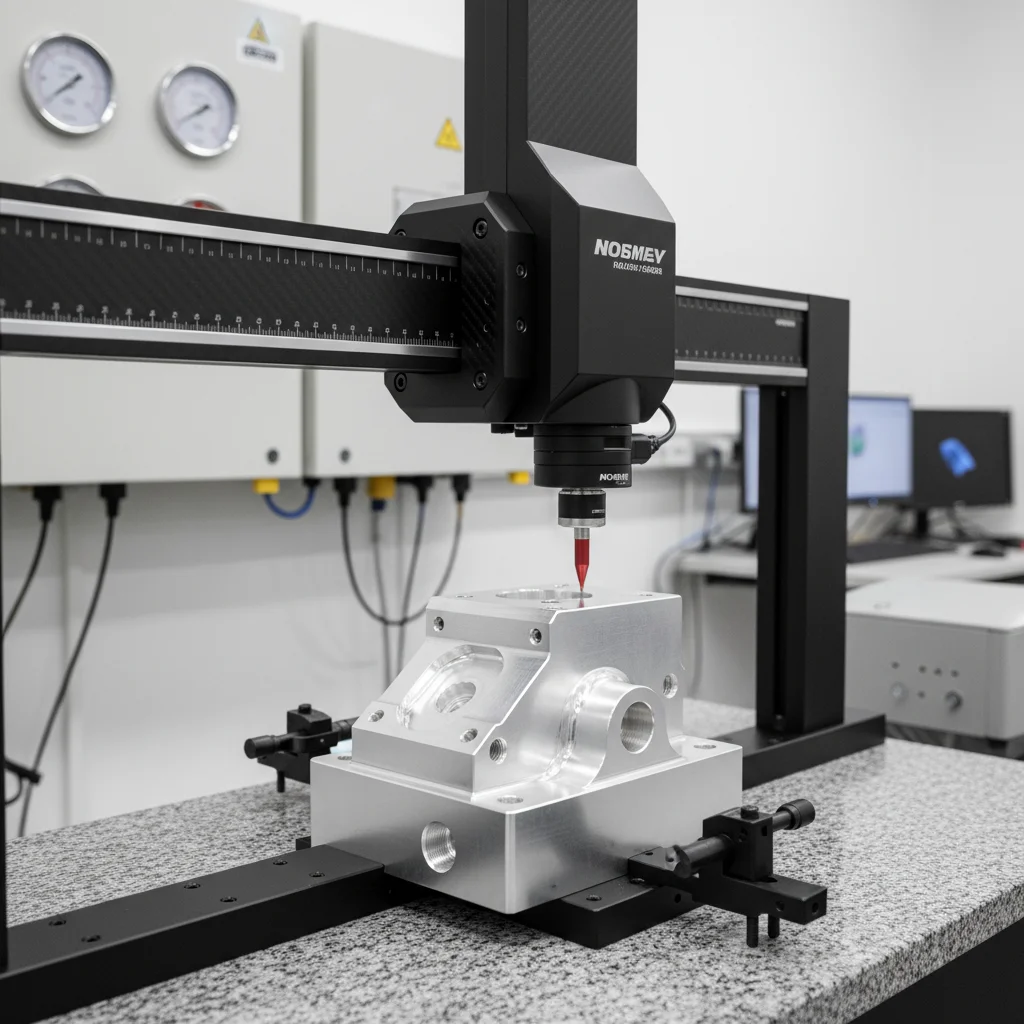
Measurement and Verification
Producing a tight-tolerance part is only half the job. Verifying it is equally critical. The primary measurement tool is the CMM (Coordinate Measuring Machine), a precision instrument that probes part surfaces and compares measured dimensions to the CAD model. For the tightest work, CMMs operate in temperature-controlled rooms because thermal expansion in metal is significant at the micron level — steel expands roughly 11 µm per meter per degree Celsius [1].
The verification workflow in a well-run tight tolerances manufacturing operation typically follows this sequence:
- First article inspection (FAI) on the initial part from each setup.
- In-process gauging at defined intervals during the production run.
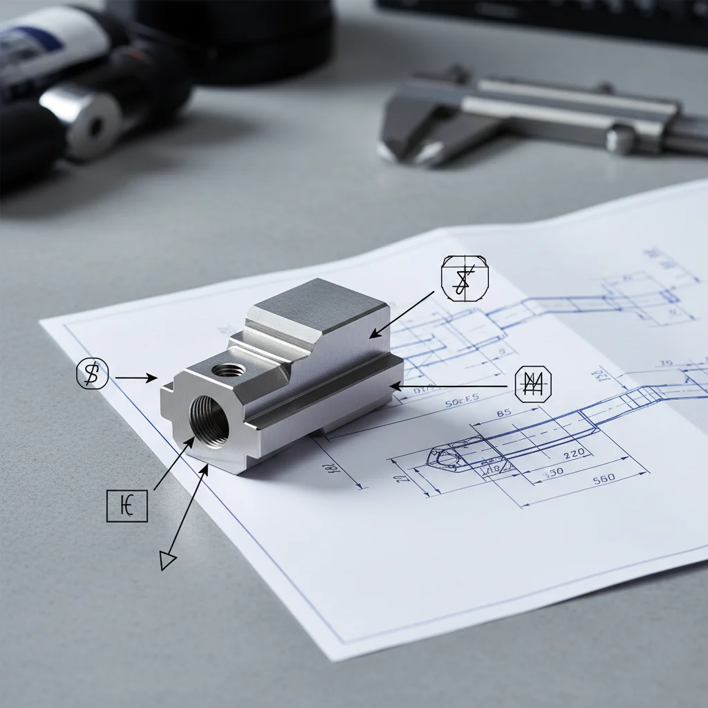
- Final CMM inspection against the drawing’s GD&T (Geometric Dimensioning and Tolerancing) callouts.
- Documentation of all measured values in an inspection report shipped with the parts.
According to research published by the Design Society, systematic tolerance analysis during the design phase — not just at inspection — is the most cost-effective way to achieve dimensional accuracy at scale [6]. Catching a tolerance problem in CAD costs nothing. Catching it after machining 500 parts costs a great deal.
Pro Tip: Always specify GD&T (Geometric Dimensioning and Tolerancing) on drawings rather than coordinate tolerances alone. GD&T communicates functional intent — flatness, perpendicularity, true position — which gives the machinist the information needed to prioritize where precision is truly required.
Key Benefits of Tight Tolerances Manufacturing
Tight tolerances manufacturing delivers measurable advantages in part quality, assembly reliability, and long-term cost reduction — provided tolerances are specified correctly from the start.
Performance, Safety, and Interchangeability
The most direct benefit is functional reliability. Parts that stay within tight dimensional limits fit together correctly, perform as designed, and don’t introduce variability into the assembled product [7]. Consider a hydraulic valve spool: a clearance that’s 0.02 mm too large causes internal leakage and pressure loss. A clearance that’s 0.02 mm too small causes the spool to seize. Only tight tolerances manufacturing delivers the consistent clearance the design requires.
Key performance benefits include:
- Interchangeability: Parts from different production batches fit without hand-fitting or selective assembly, which is essential for high-volume OEM manufacturing.
- Reduced rework and scrap: Consistent dimensions mean fewer parts rejected at final inspection. Research from Orion Industries notes that tighter tolerance control directly correlates with higher product dependability [7].
- Regulatory compliance: Medical device and aerospace components must meet dimensional specifications defined in design history files and quality plans. ISO 13485 certification, for instance, requires documented evidence that manufacturing processes consistently produce parts within specification.
- Longer service life: Precision fits reduce wear, vibration, and fatigue loading in moving assemblies, extending the operational life of the finished product.
- Easier assembly: When every part is within spec, assembly lines move faster with fewer stoppages for fit adjustments.
The Total Cost of Ownership Argument
A common misconception is that tight tolerances manufacturing is always more expensive. The unit machining cost is higher — that’s true. But the total cost of ownership often favors precision. Field failures, warranty claims, and product recalls in safety-critical industries carry costs that dwarf the incremental machining premium. According to Alco Manufacturing, tight tolerance parts play a vital role in improving component performance across multiple industries, reducing the downstream costs that loose tolerances generate [8].
At GC INDUS, we’ve found that clients who switch from lower-precision suppliers often discover their “cheaper” parts were generating hidden costs in rework, delayed assembly, and customer returns that exceeded the precision premium by a factor of two or three.
Common Challenges in Tight Tolerances Manufacturing
Tight tolerances manufacturing introduces specific technical and process challenges that standard manufacturing doesn’t face — and understanding them is the first step to avoiding costly mistakes.
Thermal Expansion, Tool Wear, and Material Behavior
Metal expands and contracts with temperature. At the micron level, this isn’t a theoretical concern — it’s a practical one. A 300 mm steel shaft will grow by approximately 3.3 µm for every 1°C rise in ambient temperature [1]. In a shop floor environment where temperature can swing 5°C to 10°C during a shift, that’s enough to push a ±0.005 mm tolerance out of spec without the machinist touching anything.
Other significant challenges include:
- Tool wear: Cutting tools wear progressively during a run. A tool that holds ±0.003 mm at the start of a batch may drift to ±0.010 mm by part 50. Scheduled tool changes and in-process gauging are essential.
- Material springback: Metals and especially plastics spring back elastically after machining. This is particularly problematic for thin-walled parts and must be compensated in the machining program.
- Fixturing and clamping forces: Over-clamping distorts thin parts during machining; they relax to an out-of-tolerance shape after release. Proper workholding design is non-negotiable for tight tolerances.
- Tolerance stackup: In assemblies with multiple components, individual part tolerances accumulate. Tolerance stackup can result in an assembly that fails even when every individual part is within spec [4]. Statistical tolerance analysis (RSS method) or worst-case analysis must be performed at the design stage.
- Surface finish interaction: Very tight tolerances and very rough surfaces are incompatible. The surface roughness Ra value must be specified in proportion to the dimensional tolerance.
The Over-Tolerancing Trap
One pitfall that’s surprisingly common: engineers specify tolerances tighter than the function actually requires, often as a safety margin. The NASA Lessons Learned database explicitly warns that excessively tight tolerances increase machining complexity and scrap rates without improving functional performance [4]. A tolerance that’s 10x tighter than needed can triple the part cost. The fix is a disciplined tolerance allocation process tied to functional requirements, not engineering conservatism.
Pro Tip: When reviewing a drawing for the first time, circle every tolerance tighter than ±0.025 mm and ask the design engineer to justify each one functionally. You’ll often find 30–50% of tight callouts can be relaxed without any impact on part performance — which directly reduces cost and lead time.
Best Practices for Tight Tolerances Manufacturing in 2026
Consistently achieving this approach in 2026 requires a system-level approach, not just better machines — it’s about process control, design collaboration, and measurement discipline working together.
Design for Manufacturability and Process Selection
The most effective place to address tight tolerances is at the design stage, before a single chip is cut. Design for Manufacturability (DFM) is a methodology that evaluates part geometry, material, and tolerance requirements against the capabilities of available manufacturing processes [9]. A DFM review will flag features that are unnecessarily difficult to machine, suggest geometry changes that make tight tolerances easier to hold, and identify where tolerance stackup is a risk.
Practical steps for achieving tight tolerances consistently:
- Select the right process for the tolerance required. Don’t try to hold ±0.002 mm with a standard 3-axis mill when a Swiss lathe or grinding operation is the appropriate process.
- Control the thermal environment. Precision machining and inspection should occur in temperature-controlled spaces. ISO 1 specifies 20°C as the standard reference temperature for dimensional measurement.
- Implement Statistical Process Control (SPC). SPC monitors key dimensions during production and signals when a process is drifting before it produces out-of-tolerance parts. It’s a core requirement under ISO 9001 quality management systems.
- Use appropriate fixturing. Purpose-built fixtures that locate the part consistently and apply minimal clamping distortion are worth the investment for tight-tolerance work.
- Verify with calibrated instruments. Micrometers, CMMs, and air gauges must be calibrated on a documented schedule. An uncalibrated gauge is worse than no gauge — it gives false confidence.
- Document everything. First article inspection reports, in-process measurement logs, and final inspection data create the traceability required by ISO 9001 and ISO 13485.
Material Selection and Post-Processing Considerations
Material choice affects achievable tolerances. Aluminum alloys like 6061-T6 machine cleanly and hold tight tolerances well. Stainless steel work-hardens during cutting, requiring sharp tools and proper speeds to maintain dimensional stability. Plastics are more problematic — they absorb moisture, creep under load, and have high thermal expansion coefficients [3].
Post-processing matters too. Heat treatment after machining can relieve residual stresses and cause dimensional changes. For tight-tolerance parts, the sequence is typically: rough machine, stress relieve, finish machine to final dimension. Surface treatments like hard anodizing add measurable thickness (typically 12–25 µm per side) and must be accounted for in the pre-treatment machining dimensions.
Our team at GC INDUS recommends always specifying whether tolerances apply before or after surface treatment on the drawing. This single clarification prevents a significant number of non-conformances in practice.
Sources & References
- Wikipedia, “Engineering Tolerance,” 2026
- Casting China, “ISO 2768: Standard Tolerances for Precision Manufacturing,” 2024
- Ensinger Precision Components, “Achieving Tight Tolerances for Critical and Complex Parts,” 2024
- NASA Lessons Learned Information System, “Vehicle Integration/Tolerance Buildup Practices,” Lesson 713
- Avanti Engineering, “CNC Machining With Tight Tolerances: What Businesses Need to Know,” 2024
- Design Society, “A Systematic Approach for Cost Optimal Tolerance Design,” 2023
- Orion Industries, “The Importance of Tight Tolerances,” 2024
- Alco Manufacturing, “The Importance of Tight Tolerance Parts in Modern Manufacturing,” 2024
- Epec Engineered Technologies, “Design Practices for CNC Machined Parts with Tight Tolerances,” 2024
- Vaporkote, “6 Tips for Holding Tight Tolerances in Manufacturing,” 2024
Frequently Asked Questions
1. Is 0.01 mm a tight tolerance?
Yes, 0.01 mm (10 microns) is firmly in the high-precision category of this approach. To put it in context, a human hair is roughly 70 microns in diameter, so 0.01 mm is about one-seventh of that. At this level, standard CNC milling is insufficient — you need precision grinding, Swiss lathe turning, or EDM, combined with CMM verification in a temperature-controlled environment. A deviation of 0.01 mm in a critical bore or shaft diameter can cause improper fits, bearing failures, or fluid leakage in hydraulic systems, making this tolerance level both technically demanding and functionally significant.
2. Is ±0.002 mm a tight tolerance?
±0.002 mm (2 microns total range of 4 microns) is an extremely tight tolerance, sitting at the upper boundary of what production CNC machining can reliably achieve. This level is typically reserved for precision bearing seats, gauge blocks, and high-performance aerospace or medical components. Achieving it requires precision grinding or honing, rigorous thermal control of the machining environment, and measurement with calibrated instruments traceable to national standards. Results may vary depending on material, part geometry, and batch size — not every shop can hold this consistently across a production run.
3. What is the tightest tolerance achievable in CNC machining?
In production CNC machining, tolerances as tight as ±0.001 mm (1 micron) are achievable with advanced equipment, proper fixturing, and environmental controls. Ultra-precision machining for semiconductor and optical applications can reach sub-micron levels, but these require specialized machines and are not standard production processes. For most industrial applications in the practice, ±0.001 mm to ±0.005 mm represents the practical precision frontier using 5-axis CNC, Swiss lathes, and precision grinding.
4. What causes tolerance stackup and how do you prevent it?
Tolerance stackup occurs when the individual dimensional variations of multiple components in an assembly accumulate, potentially causing the assembled product to fall outside functional limits even though every individual part is within its own tolerance [4]. The result can be gaps too large, interference fits that seize, or mechanisms that bind. Prevention involves performing a tolerance stackup analysis (worst-case or RSS statistical method) during the design phase, allocating tighter tolerances only to the dimensions that most affect the critical assembly dimension, and using GD&T to control geometric variation precisely.
5. What does ISO 2768 say about standard machining tolerances?
ISO 2768 defines general tolerances for linear and angular dimensions in machined parts, organized into four grades: fine (f), medium (m), coarse (c), and very coarse (v) [2]. For a 30 mm nominal dimension, ISO 2768-m allows ±0.2 mm, while ISO 2768-f allows ±0.05 mm. Any tolerance tighter than ISO 2768-f must be explicitly called out on the drawing and is, by definition, in the territory of this practice. The standard is widely used as a default tolerance specification when individual dimensions aren’t explicitly toleranced.
6. How does material choice affect achievable tolerances?
Material properties directly influence how tight a tolerance can be held in practice. Aluminum alloys machine cleanly and have predictable behavior, making them well-suited for this method. Stainless steel and titanium work-harden during cutting, requiring precise speed and feed management. Plastics and composites present the greatest challenge — they have high thermal expansion, absorb moisture, and creep under clamping force, all of which introduce dimensional instability. For the tightest tolerances, stable materials like tool steel, hardened stainless, or engineering ceramics are preferred when the application allows.
Conclusion
this strategy isn’t a niche specialty anymore. As medical devices get smaller, automotive powertrains go electric, and electronics continue to miniaturize, the ability to hold ±0.001 mm consistently has become a baseline expectation for precision suppliers. The fundamentals haven’t changed: the right process, the right environment, rigorous measurement, and disciplined design are what separate parts that pass inspection from parts that perform in the field.
Understanding where tight tolerances are genuinely needed — and where they’re over-specified — is equally important. Specifying only the precision your application requires keeps costs controlled without compromising function.
GC INDUS holds tolerances to ±0.001 mm across CNC milling, turning, 5-axis machining, Swiss lathe, EDM, wire cutting, and grinding. Backed by ISO 9001 and ISO 13485 certifications, full CMM inspection protocols, and flexible MOQs starting from a single piece, we deliver this approach for over 300 global clients in medical, aerospace, automotive, and industrial sectors. If your next project demands precision that your current supplier can’t reliably deliver, we’re ready to review your drawings and provide a fast quote.
Recommended Articles
Explore more from our content library: