Book Appointment Now

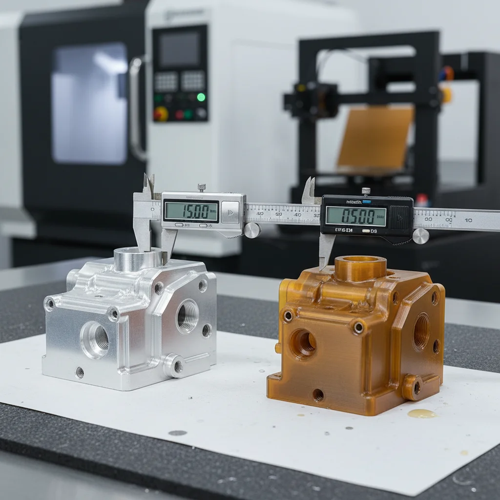
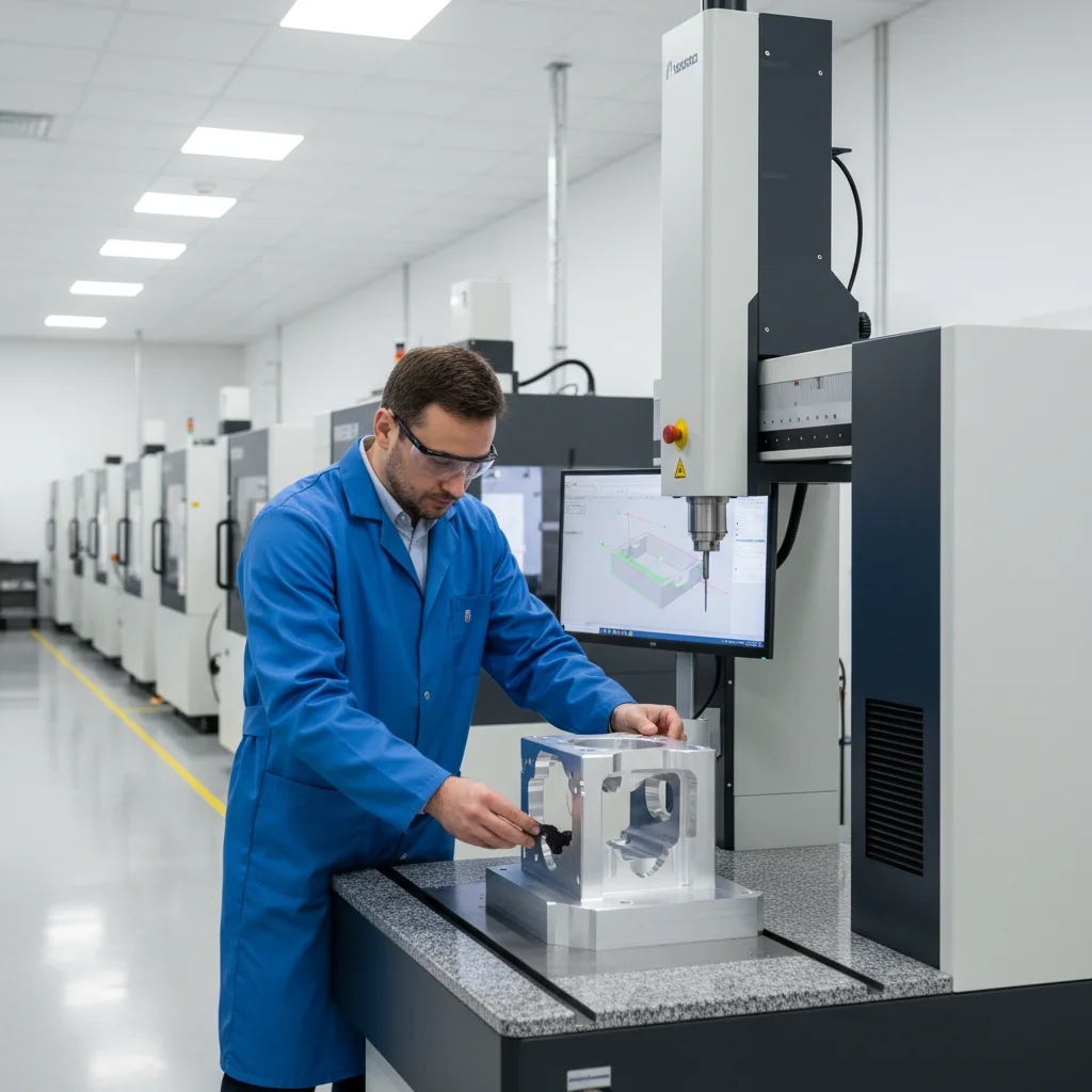
 inspecting a precision plastic injection molded part, 2D dimensional quality control check")
Rapid Prototyping in Precision Engineering Explained
Learn how rapid prototyping precision engineering accelerates product development with tight tolerances, faster iteration, and lower costs in 2026. Discover.
| Key Insight | Explanation |
|---|---|
| Rapid prototyping cuts iteration time | Physical prototypes can be produced in hours or days instead of weeks, allowing engineers to catch design flaws early. |
| Precision tolerances are achievable at prototype stage | CNC machining enables tolerances as tight as ±0.001mm even on single-piece prototype runs, matching production-grade specs. |
| Multiple methods serve different needs | CNC machining, SLA, SLS, and FDM each offer different trade-offs between speed, material accuracy, and dimensional precision. |
| Medical and aerospace demand the highest standards | ISO 13485 and AS9100 compliance is required for prototypes destined for regulated industries, not just final production parts. |
| Low MOQ unlocks prototype-to-production continuity | Suppliers offering MOQs from 1 piece let engineering teams iterate without committing to costly minimum runs. |
| DFM feedback reduces downstream costs | Design for Manufacturability analysis during prototyping prevents expensive tooling changes and tolerance violations at scale. |
Your OEM client just approved the design. Now they want a functional prototype with ±0.005mm tolerances in two weeks. That’s where rapid prototyping precision engineering earns its place in the modern product development cycle. Rapid prototyping precision engineering is the practice of producing accurate physical models or functional components from digital designs within compressed timelines, using processes capable of holding tight dimensional tolerances. It bridges concept and production. And in 2026, it’s no longer a luxury reserved for large manufacturers with deep R&D budgets.
This article covers what rapid prototyping precision engineering actually involves, how the core processes work, which methods suit which applications, and what mistakes to avoid. You’ll also find a practical FAQ section addressing the questions engineers and procurement teams ask most often.
What Is Rapid Prototyping Precision Engineering?
Rapid prototyping precision engineering is the accelerated production of dimensionally accurate physical parts directly from 3D CAD data, using manufacturing processes that maintain engineering-grade tolerances throughout the build. It combines speed with measurable dimensional control, which is what separates it from general rapid prototyping used in product design or UX work.
Defining the Core Concept
According to Wikipedia’s overview of rapid prototyping [1], the field originated as a group of techniques to quickly fabricate scale models using 3D CAD data. In precision engineering contexts, that definition expands significantly. The prototype isn’t just a visual model. It’s a functional component that must perform under load, fit mating parts, and often survive regulatory inspection.
Precision prototyping methods include:
- CNC machining (computer numerical control): Subtractive process that removes material to achieve tight tolerances, often ±0.001mm to ±0.01mm
- Stereolithography (SLA): Photopolymer resin cured by UV laser, offering high surface finish and dimensional accuracy
- Selective Laser Sintering (SLS): Powder-bed fusion process for functional polymer and metal prototypes
- Direct Metal Laser Sintering (DMLS): Metal additive process capable of complex geometries with good mechanical properties
- Wire EDM (electrical discharge machining): Removes material via controlled electrical sparks, ideal for hard metals and intricate profiles
Why Precision Matters at the Prototype Stage
Many engineers assume tight tolerances only matter at production. That assumption is costly. A prototype built to loose tolerances won’t reveal fit problems, assembly interference, or stress concentrations that appear in the final part. The Georgia Tech Matrix Lab’s IPD-RP framework [2] explicitly identifies precision and surface finish as primary desirability criteria in the prototyping process, alongside time and cost efficiency.
In regulated industries, the stakes are even higher. Medical device prototypes destined for clinical evaluation, for example, must comply with ISO 13485 quality management requirements from the earliest physical iteration, not just at final production sign-off.
Pro Tip: Always specify your target production tolerance when requesting a prototype, not just “as accurate as possible.” A supplier who knows your final spec can flag DFM (Design for Manufacturability) issues before they become tooling problems.
How Rapid Prototyping Works in Precision Engineering
The rapid prototyping process in precision engineering follows a structured sequence from digital design to inspected physical part, typically completed in days rather than the weeks traditional tooling requires.
The Step-by-Step Process
Researchers at Pacific Northwest National Laboratory (PNNL) [3] describe the core advantage clearly: their team can move from concept to physical prototype in hours or days, with hardware solutions updated at speeds that traditional manufacturing can’t match. That speed depends on a disciplined process.
- CAD file preparation: The engineer produces a 3D model in STEP or IGES format, with GD&T (geometric dimensioning and tolerancing) callouts defined
- DFM review: The manufacturer checks the design for features that are difficult or impossible to machine, such as internal sharp corners, insufficient wall thickness, or undercuts that require special tooling
- Process selection: Based on material, tolerance, quantity, and lead time, the appropriate method is chosen (CNC, SLA, SLS, EDM, etc.)
- Toolpath programming: For CNC, CAM (computer-aided manufacturing) software generates the toolpaths that guide the machine
- Machining or build: The part is produced, with in-process checks at critical dimensions
- Post-processing: Deburring, surface treatment, heat treatment, or coating as required by the specification
- Inspection and reporting: CMM (coordinate measuring machine) or optical measurement confirms dimensional compliance; a full inspection report is issued
- Delivery: The finished prototype ships with documentation ready for engineering review or regulatory submission
Choosing the Right Method for Your Application
Not every rapid prototyping method delivers the same precision. The table below compares the most common processes used in precision engineering contexts [4].
| Process | Typical Tolerance | Best For | Material Options |
|---|---|---|---|
| CNC Milling / Turning | ±0.001mm – ±0.01mm | Functional metal prototypes, tight-fit assemblies | Aluminum, steel, stainless, titanium, plastics |
| Wire EDM | ±0.002mm – ±0.005mm | Hard metals, complex 2D profiles, tool steels | Hardened steel, carbide, inconel |
| SLA (Stereolithography) | ±0.05mm – ±0.1mm | Visual models, form-fit testing, medical housings | Photopolymer resins |
| SLS (Selective Laser Sintering) | ±0.1mm – ±0.3mm | Functional polymer parts, complex geometries | Nylon, TPU, glass-filled polymers |
| DMLS (Direct Metal Laser Sintering) | ±0.05mm – ±0.1mm | Complex metal geometries, aerospace brackets | Stainless steel, titanium, aluminum alloys |
As SixDe explains in their precision machining guide [5], CNC machining uses computer numerical control to guide cutting tools, shaping material to the required form with repeatable accuracy. It remains the dominant choice when functional prototypes must match production-grade mechanical properties.
Key Benefits of Rapid Prototyping for Precision Parts
Rapid prototyping precision engineering delivers measurable advantages across cost, time, and quality, particularly for teams managing tight development schedules and regulatory requirements.
Speed, Cost, and Quality Gains
The primary goal of rapid prototyping is to accelerate time to market and reduce the cost of failure by enabling multiple design iterations [6]. In practice, that means catching a tolerance stack-up issue on a $200 prototype rather than a $20,000 production tool. The compounding benefit is significant.
- Faster design validation: Physical parts reveal fit, function, and assembly issues that CAD models miss. Engineers can complete 3-5 iteration cycles in the time traditional tooling requires for one
- Lower cost of design changes: Modifying a CNC program costs hours. Modifying a production mold costs weeks and tens of thousands of dollars
- Regulatory documentation support: A precision prototype with a full CMM inspection report supports design verification (DV) testing required by FDA 21 CFR Part 820 and ISO 13485
- Supply chain risk reduction: Prototyping with your production supplier (rather than a separate prototype house) confirms that your production partner can actually hold the specified tolerances
- Investor and client confidence: A functional, finished prototype communicates engineering credibility in a way that a CAD render simply doesn’t
Industry-Specific Advantages
Different sectors extract different value from precision prototyping. ARRK Engineering notes [7] that for companies prioritizing precision, quality, and time-to-market, rapid prototyping has become an indispensable part of modern engineering. That’s especially true in three sectors:
- Medical devices: Surgical instruments and implant components require biocompatible materials and surface finishes that only precision machining delivers at the prototype stage
- Aerospace and defense: The Johns Hopkins University Applied Physics Laboratory [8] uses rapid prototyping to design, fabricate, test, and deploy prototypes for defense and space applications, where performance under extreme conditions is non-negotiable
- Automotive: Tier-1 suppliers use precision prototypes to validate assembly fits before committing to production tooling for components with sub-millimeter clearances
At GC INDUS, we’ve found that clients who prototype with us using the same CNC processes as their production run see significantly fewer tolerance surprises when they scale. The process parameters are already validated. That continuity matters.
Pro Tip: Request a First Article Inspection (FAI) report with your prototype. This document, standard in aerospace under AS9102, provides a complete dimensional record that you can compare directly against your production parts later. It’s inexpensive to add and invaluable during qualification.
Common Challenges and Mistakes in 2026
Rapid prototyping precision engineering fails most often not because of machine capability but because of decisions made before the first cut. As of 2026, these are the pitfalls that consistently derail prototype programs.
Design and Specification Errors
A common mistake is specifying tolerances tighter than the application actually requires. Over-tolerancing drives up machining time, increases scrap rates, and can make a prototype 3-4x more expensive without improving functional performance. Industry analysts suggest that 30-40% of precision prototype cost overruns stem from tolerance specifications copied from legacy drawings without engineering review.
- Ignoring DFM feedback: Suppliers flag features like blind holes with depth-to-diameter ratios above 10:1 or internal radii smaller than available tooling. Ignoring this feedback guarantees delays
- Using the wrong process for the material: Attempting to SLS a prototype that requires metal mechanical properties, or CNC machining a geometry that needs additive manufacturing’s internal lattice capability
- Skipping post-processing in the prototype spec: A prototype without the specified surface treatment or heat treatment won’t reveal how those processes affect final dimensions
- Separating prototype and production suppliers: Prototyping with a different vendor than your production partner means your production supplier has never validated their ability to hold your tolerances
Process and Quality Oversights
One pitfall to watch for is inadequate inspection planning. A precision prototype without a dimensional inspection report is essentially a guess. The Journal of Advanced University of Science and Management Technology [9] research on high-precision, low-cost prototyping highlights that process control and measurement are as critical as the build process itself.
- No in-process inspection: Waiting until final inspection to discover a dimension is out of tolerance wastes the entire build time
- Incomplete material certification: Prototypes for medical or aerospace applications require material test reports (MTRs) and certificates of conformance, not just a verbal assurance
- Underestimating lead time for surface treatments: Anodizing, electroless nickel plating, or passivation add days to the schedule and can affect final dimensions by several microns
In one project we handled for a medical device OEM, the engineering team had specified a hard anodize coating on an aluminum housing without accounting for the 0.012-0.025mm thickness the coating adds per surface. The result was an interference fit that failed assembly. Catching that in the prototype stage saved weeks of production rework.
Best Practices for Rapid Prototyping Precision Engineering in 2026
Effective rapid prototyping precision engineering in 2026 requires a disciplined approach that aligns design intent, process selection, quality requirements, and supplier capability from the start.
Selecting the Right Supplier and Process
Protolabs’ manufacturing guide [10] outlines the key trade-offs between prototyping processes and recommends evaluating both advantages and shortcomings before committing. That advice holds in 2026. Your checklist when evaluating a precision prototyping supplier should include:
- Confirmed tolerance capability for your specific process and material combination
- ISO 9001 certification for quality management (minimum requirement)
- ISO 13485 certification if the prototype is for a medical device application
- In-house CMM or optical measurement capability with documented inspection protocols
- DFM review offered before quoting, not just after order placement
- Flexible MOQ, ideally from 1 piece, so you can iterate without minimum run commitments
- Material certification capability (MTRs, certificates of conformance)
Engineering and Documentation Best Practices
The West Texas A&M University Rapid Prototyping Center [11] emphasizes that high-resolution, precise functional parts require not just capable machines but also proper design preparation. Follow these steps for every precision prototype program:
- Define your critical-to-function (CTF) dimensions separately from general tolerances. Not every dimension needs ±0.001mm
- Submit STEP files with a 2D drawing that includes GD&T callouts. Never rely on a 3D model alone for tolerance communication
- Request a DFM report before approving the quote. Resolve all flagged issues before the build starts
- Specify the complete surface condition: roughness (Ra value), coating, and heat treatment state
- Require a dimensional inspection report with actual measured values, not just pass/fail
- Compare prototype inspection data to your production tolerance limits, not just the prototype spec. This confirms production feasibility
Pro Tip: Our team at GC INDUS recommends treating your first prototype as a process validation exercise, not just a design check. Ask your supplier to document the exact machine, tooling, and cutting parameters used. If those parameters are replicated in production, your dimensional results will be predictable.
Formlabs’ comprehensive guide to rapid prototyping [12] reinforces that the choice of technique depends heavily on the required mechanical properties and dimensional accuracy of the finished part. In precision engineering, that selection decision is the most consequential one you’ll make in the entire prototype program.
Results may vary based on material, geometry complexity, and supplier capability. The practices above represent a strong baseline, but your specific application may require additional steps, particularly in highly regulated industries.
Sources & References
- Wikipedia, “Rapid Prototyping,” 2026
- Georgia Tech Matrix Lab, “IPD-RP: Innovative Process Design for Rapid Prototyping,” 2026
- Pacific Northwest National Laboratory, “Rapid Prototyping,” 2026
- Fast Precision, “Rapid Prototyping Explained — How Engineers Turn Ideas into Parts,” 2026
- SixDe, “What Is Rapid Prototyping for Precision Machining?”, 2026
- Fresh Consulting, “What Is Rapid Prototyping? Methods, Strategy, and Best Practices,” 2026
- ARRK Engineering, “How Is Rapid Prototyping Changing The Engineering Design Process,” 2026
- Johns Hopkins University Applied Physics Laboratory, “Rapid Prototyping,” 2026
- Journal of Advanced University of Science and Management Technology, “A High Performance, High Precision, Low Cost Rapid Prototyping,” 2026
- Protolabs, “Selecting a Rapid Prototyping Process: Manufacturing Guide,” 2026
- West Texas A&M University, “Rapid Prototyping Center,” 2026
- Formlabs, “What Is Rapid Prototyping? Methods, Tools and Examples,” 2026
Frequently Asked Questions
1. What is the 8-6-4 rapid prototype method?
The 8-6-4-2 rapid prototype method is a time-boxed sketching and feedback technique used in product design ideation. Designers sketch concepts for 8 minutes, then 6 minutes, then 4 minutes, with short 2-minute feedback sessions between each round. The decreasing time pressure forces progressively more decisive design choices and rapid iteration, making it useful for early-stage concept development. This method is distinct from rapid prototyping precision engineering, which involves physical part production, not sketching.
2. Who owns Rapid Manufacturing?
As of 2026, Rapid Manufacturing Group, LLC was acquired by Proto Labs, Inc. (NYSE: PRLB), a technology-enabled manufacturing company. Rapid Manufacturing Group was a New Hampshire-based custom parts supplier specializing in quick-turn sheet metal fabrication and CNC machining. The acquisition expanded Proto Labs’ sheet metal capabilities and customer base. Note that “rapid manufacturing” as a general term refers to any accelerated production process, not a single company, and many manufacturers offer rapid manufacturing services independently.
3. What are the 4 types of prototypes?
The four main prototype categories are feasibility prototypes (testing whether a concept can work technically), low-fidelity user prototypes (rough representations for early user feedback), high-fidelity user prototypes (detailed, near-final representations for validation testing), and live-data prototypes (functional versions connected to real systems or data). In rapid prototyping precision engineering specifically, the focus is on high-fidelity functional prototypes built to production-equivalent tolerances and materials, ensuring that dimensional and mechanical validation data is directly applicable to the production design.
4. What is the difference between rapid prototyping and precision machining?
Rapid prototyping emphasizes speed of iteration, producing physical parts quickly from digital designs. Precision machining emphasizes dimensional accuracy, holding tight tolerances through controlled subtractive processes. Rapid prototyping precision engineering combines both: using CNC machining, EDM, and other high-accuracy processes within compressed timelines. The result is a prototype that is both fast to produce and dimensionally accurate enough to validate production specifications, rather than choosing one priority over the other.
5. Why is rapid prototyping important in engineering?
Rapid prototyping is important because it compresses the design-test-revise cycle from months to days. Engineers discover fit issues, assembly conflicts, and performance problems on inexpensive prototypes rather than after production tooling is committed. For precision engineering applications, this is especially critical because tolerance stack-ups, surface finish requirements, and material behavior under load are difficult to fully predict in simulation alone. Physical prototypes provide ground truth that CAD models can’t replicate, reducing downstream cost and schedule risk.
6. What materials are used in rapid prototyping for precision engineering?
Common materials include aluminum alloys (6061, 7075), stainless steel (304, 316), tool steels, titanium, magnesium alloys, and engineering plastics such as PEEK, Delrin, and nylon. The choice depends on the functional requirements of the prototype. For medical device applications, biocompatible materials with documented material test reports are required. For structural aerospace components, certified aluminum and titanium alloys are standard. CNC machining supports the widest material range with the tightest tolerances, making it the most versatile rapid prototyping method for precision engineering.
7. How tight can tolerances be in rapid prototyping precision engineering?
Using CNC milling, turning, and grinding, tolerances as tight as ±0.001mm are achievable even on single-piece prototype runs. Wire EDM can hold ±0.002mm to ±0.005mm on complex profiles in hard metals. Additive methods like SLA achieve ±0.05mm to ±0.1mm, which is sufficient for form-fit testing but not for tight-clearance functional assemblies. The tightest tolerances require temperature-controlled machining environments, high-precision tooling, and thorough in-process inspection to maintain dimensional stability throughout the build.
Conclusion
this approach isn’t just about making parts faster. It’s about making the right decisions earlier, with physical evidence rather than assumptions. The combination of compressed timelines and engineering-grade dimensional accuracy gives development teams the information they need to commit to production with confidence.
The methods, best practices, and pitfall avoidance strategies covered here apply whether you’re developing a surgical instrument, an automotive bracket, or an aerospace housing. The fundamentals are consistent: specify tolerances based on function, choose the right process for your material and geometry, inspect every prototype to production standards, and work with a supplier who can carry that capability from your first prototype through your full production run.
GC INDUS delivers exactly that continuity. We hold tolerances to ±0.001mm across CNC milling, turning, 5-axis machining, Swiss lathe, wire cutting, and EDM. We accept orders from 1 piece, so your prototype and your production run are built with the same processes, the same inspection protocols, and the same quality standards. ISO 9001 and ISO 13485 certified, trusted by 300+ companies globally. If you’re ready to move from CAD to a precision-inspected part, we’re ready to quote.
Recommended Articles
Explore more from our content library: