Book Appointment Now


Multi-Axis CNC Machining: A Complete 2026 Guide
Learn how multi-axis CNC machining works, its key benefits, common challenges, and best practices for 2026. Comprehensive guide for engineers and buyers.
| Key Insight | Explanation |
|---|---|
| Definition | Multi-axis CNC machining uses computer-controlled tools that move in four or more directions, enabling complex part geometries in a single setup. |
| Axis Range | Machines range from 3-axis to 12-axis configurations; 5-axis is the most widely adopted for precision work as of 2026. |
| Precision Capability | Advanced multi-axis machines hold tolerances as tight as ±0.001mm, critical for aerospace, medical, and automotive applications. |
| Setup Efficiency | A single multi-axis setup replaces multiple sequential operations, reducing fixturing time and cumulative error. |
| Industry Applications | Used across medical devices, aerospace components, automotive parts, and precision electronics enclosures. |
| Quality Standards | ISO 9001 and ISO 13485 certifications are key quality benchmarks for shops offering multi-axis CNC services. |
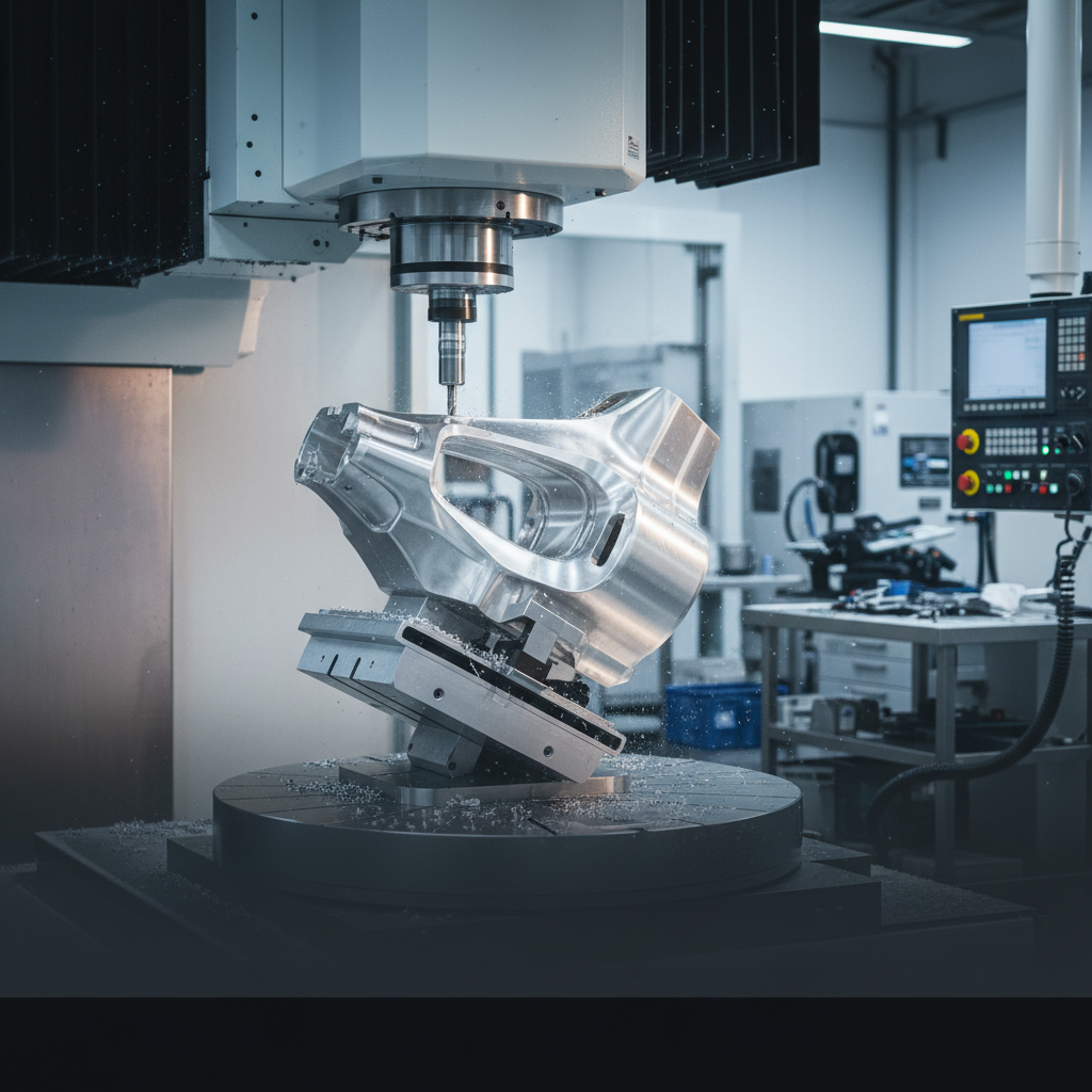
Your aerospace client just sent over a turbine blade design with compound curves, internal cooling channels, and a surface finish requirement that rules out any secondary operations. Your current 3-axis vendor says it’ll take four separate setups and 10 weeks. Multi-axis CNC machining solves that problem in one. Multi-axis CNC machining is a manufacturing process where computer-controlled cutting tools move in four or more directions simultaneously, allowing complex geometries to be completed in a single setup with exceptional accuracy. It’s the foundation of modern precision manufacturing. In this guide, you’ll learn exactly how it works, why it matters, where it’s applied, and what separates shops that do it well from those that don’t.
What Is Multi-Axis CNC Machining?
Multi-axis CNC machining is a process where a cutting tool and workpiece move along four or more controlled axes simultaneously, enabling complex 3D geometries that conventional 3-axis equipment simply can’t reach in a single setup.
Defining the Axes: From 3 to 12
Standard 3-axis CNC milling moves along the X, Y, and Z linear axes. That covers a lot of parts, but it hits a wall fast with undercuts, compound angles, and curved surfaces. Multi-axis systems add rotational axes (typically labeled A, B, and C) that tilt or rotate either the tool, the workpiece, or both. According to Wikipedia’s overview of multiaxis machining, machines can range from 4-axis configurations up to 9-axis and beyond when turning and milling are combined [1].
As Fictiv’s comparison of 3-axis to 12-axis machines details, each additional axis expands the range of machinable features without requiring the operator to reposition the part [2]. That matters enormously for precision: every time you re-fixture a workpiece, you introduce potential alignment error.
Here’s a quick breakdown of the most common configurations:
| Configuration | Axes | Typical Applications | Complexity Level |
|---|---|---|---|
| 3-Axis | X, Y, Z | Flat parts, simple pockets, drilling | Basic |
| 4-Axis | X, Y, Z + A (rotation) | Cylindrical parts, helical features | Intermediate |
| 5-Axis | X, Y, Z + A, B or C | Aerospace, medical implants, turbines | Advanced |
| 9-Axis (Mill-Turn) | Multiple linear + rotary | Complex turned/milled hybrids | High |
| 12-Axis | Dual spindle/turret combos | High-volume complex parts, Swiss-style | Specialist |
Why 5-Axis Dominates in 2026
Five-axis machining has become the industry standard for precision work. Haas Automation, one of the largest machine tool builders globally, describes 5-axis as the configuration that balances capability, programming complexity, and cost for most precision applications [3]. As of 2026, 5-axis machining centers are found in virtually every serious precision shop serving aerospace, medical, and automotive clients.
Purdue University’s curriculum on multi-axis CNC machines notes that the increased range of motion allows a single machine to perform milling, holemaking, and turning operations that would otherwise require three or four separate setups [4]. That consolidation is where the real efficiency gains come from.
How Multi-Axis CNC Machining Works
Multi-axis CNC machining works by translating a digital CAD model into coordinated tool paths across multiple simultaneous axes, guided by CAM software and executed by a CNC controller with sub-micron precision.
The Process: From CAD File to Finished Part
The workflow is more involved than 3-axis machining, but the logic is straightforward. Here’s how a typical multi-axis job runs:
- CAD Design: The engineer creates a 3D model (usually in STEP or IGES format) with all geometric features, tolerances, and surface finish requirements defined.
- CAM Programming: A CAM (Computer-Aided Manufacturing) programmer imports the model and generates tool paths. For 5-axis work, this means defining how the tool tilts and rotates to reach every surface. Software like Mastercam or Siemens NX handles the complex math automatically.
- Post-Processing: The CAM output is converted into G-code, the language the CNC controller reads. Each machine has a specific post-processor that formats the code correctly.
- Setup and Fixturing: The workpiece is clamped once. The operator verifies datum points and tool offsets. This single-setup principle is what separates multi-axis from conventional sequential machining.
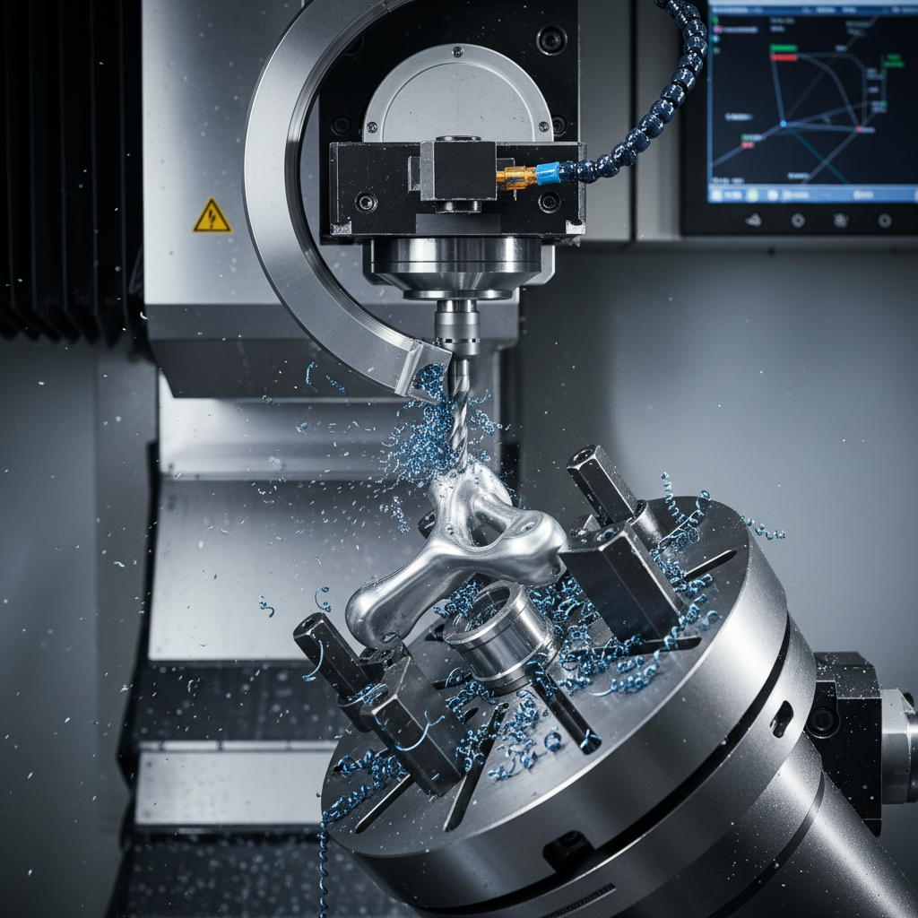
- Machining: The controller executes the program. The spindle, table, and rotary axes move simultaneously, maintaining the tool at the optimal cutting angle at every point along the path.
- In-Process Inspection: Probing cycles check critical dimensions mid-program, allowing real-time compensation before the part comes off the machine.
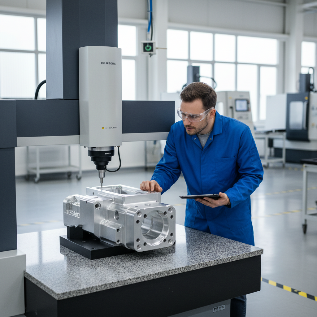
- Final Inspection: The finished part is measured on a CMM (Coordinate Measuring Machine) against the original CAD model.
Pro Tip: When programming 5-axis tool paths, always simulate the full program in your CAM software before running it on the machine. Collision detection in simulation catches gouges and fixture crashes that would otherwise destroy an expensive workpiece and potentially damage the spindle.
Simultaneous vs. Indexed Multi-Axis Machining
There’s an important distinction that buyers often miss. Simultaneous (or continuous) multi-axis machining moves all axes at the same time throughout the cut, producing smooth compound curves. Indexed (or positional) multi-axis machining rotates the part to a new angle, locks it, then cuts with standard 3-axis moves. Both are valid. Indexed machining is simpler to program and sufficient for many parts. Simultaneous machining is needed for truly complex surfaces like turbine blades or orthopedic implants.
According to Mastercam’s technical overview of multiaxis machining, the choice between simultaneous and indexed depends on part geometry, required surface finish, and the shop’s programming expertise [5]. In practice, most precision shops use a combination of both within a single program.
Key Benefits of Multi-Axis CNC Machining
The core benefit of this approach is the ability to produce complex, tight-tolerance parts in fewer setups, which directly reduces cost, lead time, and accumulated dimensional error.
Precision, Speed, and Part Complexity
The advantages compound quickly once you understand the mechanics. Here’s what multi-axis machining actually delivers:
- Higher geometric accuracy: Fewer setups mean fewer opportunities for fixturing error to stack up. Each re-clamping operation on a 3-axis machine introduces potential misalignment. Multi-axis eliminates most of those transitions.
- Better surface finish: The tool can maintain a consistent cutting angle relative to the workpiece surface, reducing scallop height and improving Ra (surface roughness average) values without extra finishing passes.
- Shorter tool overhangs: By tilting the workpiece toward the tool rather than using a longer tool to reach deep features, multi-axis setups reduce tool deflection. Less deflection means tighter tolerances and longer tool life.
- Reduced lead times: Consolidating four setups into one cuts handling time, queue time between operations, and the risk of a part getting lost or damaged between machines.
- Ability to machine undercuts: Features that are physically unreachable from a fixed angle (undercuts, deep pockets with angled walls, internal channels) become accessible when the part can rotate to present those surfaces to the tool.
- Compatibility with difficult materials: Titanium, Inconel, and hardened steels require optimized cutting angles to manage heat and tool wear. Multi-axis machining maintains that optimal angle throughout the cut.
Industry analysts at AdvancedManufacturing.org note that multi-axis machining has become one of the clearest signals of a shop’s readiness for complex parts, shorter lead times, and stronger competitive positioning in the precision manufacturing market [6].
Industry Applications Where It Matters Most
this isn’t a universal solution for every part. But for certain industries and geometries, it’s the only practical option:
- Aerospace: Structural airframe components, turbine blades, and engine housings with compound curves and strict weight tolerances.
- Medical devices: Orthopedic implants (hip cups, spinal cages), surgical instruments, and dental components requiring biocompatible materials and mirror finishes.
- Automotive: Powertrain components, suspension knuckles, and EV motor housings where tight bore tolerances and complex porting geometries are standard.
- Defense and optics: Sensor housings, mirror mounts, and precision gimbals requiring extreme dimensional stability.
- Electronics: Heat sinks, connector bodies, and RF shielding enclosures with fine features and tight flatness requirements.
A medical device client we worked with recently needed a titanium spinal implant with internal lattice channels and a surface finish of Ra 0.8 µm. Three-axis machining would have required six setups and extensive hand-finishing. With 5-axis it, we completed the geometry in two setups and hit the surface finish specification without any secondary operations.
Pro Tip: If your part has features on more than two faces, or any surface that isn’t parallel or perpendicular to the primary datum, request a 5-axis quote. The setup savings almost always offset the higher hourly machine rate, especially on parts with tolerances tighter than ±0.05mm.
Common Challenges in Multi-Axis CNC Machining
The main challenges in this method are programming complexity, collision risk, fixturing design, and the higher skill requirements for both operators and programmers compared to 3-axis work.
Programming and Collision Risk
Five-axis programming is genuinely harder than 3-axis. The tool, spindle head, rotary table, and fixture all move simultaneously, and any one of them can collide with another if the program isn’t verified carefully. A common mistake is skipping full machine simulation in CAM software and relying only on tool-path visualization. Tool-path simulation shows where the cutter goes. Machine simulation shows whether the spindle head crashes into the fixture clamp on the way there.
According to RapidDirect’s technical guide on multi-axis machining, programming errors and collision events are the leading causes of unplanned downtime on multi-axis machines [7]. The fix is straightforward: always run full machine simulation, and build in generous clearance planes between operations.
Other programming pitfalls include:
- Gimbal lock: A configuration where two rotary axes align and the machine loses a degree of freedom. Good CAM software avoids this automatically, but it’s worth understanding.
- Underestimating cycle time: Multi-axis programs often have more tool changes and repositioning moves than expected. Verify cycle time in simulation before committing to a delivery date.
- Tool length compensation errors: On 5-axis machines, tool length errors have a larger impact on positional accuracy than on 3-axis machines because the error projects through the rotary axis geometry.
Fixturing and Workholding Complexity
One of the less-discussed challenges is workholding. To take full advantage of multi-axis access, the fixture must not block any of the surfaces you need to machine. That sounds obvious, but designing a fixture that holds the part rigidly while leaving all five faces accessible is a real engineering problem.
In practice, from experience working with complex aerospace castings, the workholding design often takes as long as the tool-path programming. A poorly designed fixture that vibrates or shifts under cutting forces will destroy surface finish and blow tolerances, no matter how good the machine is.
Research published in the Journal of Intelligent Machinery highlights that fixturing strategy is among the top factors affecting dimensional accuracy in multi-axis CNC operations, particularly for thin-walled and asymmetric components [8].
Best Practices for Multi-Axis CNC Machining in 2026
The best practices for this strategy in 2026 center on DFM (Design for Manufacturability) collaboration, rigorous simulation before cutting, in-process probing, and choosing a supplier with verified quality certifications.
Design and Programming Best Practices
Getting the most from multi-axis machining starts before the program is written. Here are the practices that consistently deliver the best results:
- Engage DFM review early: Share your CAD model with your machining partner before finalizing the design. Small geometry changes, like adding a radius to a sharp internal corner or adjusting a wall thickness, can dramatically simplify programming and reduce cycle time.
- Specify tolerances intentionally: Don’t apply ±0.01mm tolerances to every feature. Identify the truly critical dimensions (bore diameters, mating surfaces, datum features) and tolerance those tightly. Leave looser tolerances on non-critical geometry to reduce machining time and cost.
- Use stock models in CAM: Always program from an accurate stock model that reflects the actual raw material or casting you’re starting with. Machining “air” wastes time; machining unexpected stock causes tool breakage.
- Implement in-process probing: Modern CNC controllers support on-machine probing cycles that check critical dimensions mid-program. This catches drift before it becomes scrap.
- Verify thermal compensation: Multi-axis machines run hot during long programs. Thermal growth in the spindle and structure affects accuracy. Use machines with active thermal compensation, or schedule rough and finish operations to allow temperature stabilization.
- Maintain a calibrated post-processor: The post-processor translates CAM output into machine-specific G-code. An outdated or incorrect post-processor is a hidden source of errors that’s difficult to diagnose.
Supplier Selection and Quality Assurance
Choosing the right multi-axis machining partner is as important as the design itself. Here’s what to look for:
- ISO 9001 certification: This confirms the supplier operates a documented quality management system (QMS) with traceable processes. It’s the baseline requirement for any serious precision work.
- ISO 13485 certification: If your parts go into medical devices, this certification is non-negotiable. It adds medical-specific requirements around risk management, sterility, and traceability on top of ISO 9001.
- CMM inspection capability: Ask for inspection reports, not just a certificate of conformance. A supplier with in-house CMM capability can provide dimensional data for every critical feature.
- Flexible MOQ: Prototype quantities (1-10 pieces) and production quantities (1,000+ pieces) have very different cost structures. A supplier who can handle both without requiring you to change vendors saves significant time and qualification effort.
- Material traceability: For aerospace and medical applications, you need full material certifications (mill certs) traceable to the raw stock used in your parts.
At GC INDUS, we’ve found that clients who share full CAD models and tolerance callouts upfront, rather than just 2D drawings, consistently get faster quotes, more accurate pricing, and fewer surprises at first article inspection. The data is already there. Use it.
Pro Tip: When evaluating a multi-axis machining supplier, ask specifically whether they use simultaneous 5-axis or only indexed (positional) 5-axis. For complex organic surfaces, simultaneous capability matters. For most prismatic parts with angled features, indexed 5-axis is sufficient and often more cost-effective.
Sources & References
- Wikipedia, “Multiaxis Machining”, 2026
- Fictiv, “3-Axis to 12-Axis: CNC Milling Machine Capabilities Compared”, 2026
- Haas Automation Inc., “Multi-Axis CNC Machining Solutions”, 2026
- Purdue University, “Introduction to Multi-Axis CNC Machines 217”, 2026
- Mastercam, “Multiaxis Machining 101: How It Works and Its Benefits”, 2026
- AdvancedManufacturing.org, “Inside the Craft of Multi-Axis Machining”, 2026
- RapidDirect, “What is Multi-axis Machining? Why Precision Matters”, 2026
- Mason Publishing, Journal of Intelligent Machinery, “An Exploration of Multi-Axis CNC Machining Technology”, 2026
- MakerVerse, “Multi-Axis CNC Machining Explained”, 2026
- DaCruz Manufacturing, “What is Multi-Axis Machining?”, 2026
Frequently Asked Questions
1. What is multi-axis CNC machining in simple terms?
this approach is a computer-controlled manufacturing process where the cutting tool and workpiece move along four or more axes simultaneously. This allows a machine to reach complex surfaces and angles in a single setup, rather than repositioning the part multiple times. It’s the standard approach for producing parts with curves, undercuts, or features on multiple faces, as explained in detail by DaCruz Manufacturing and MakerVerse.
2. What is the difference between 3-axis and 5-axis CNC machining?
Three-axis machining moves the tool along X, Y, and Z linear axes only, which limits access to surfaces that aren’t facing upward. Five-axis machining adds two rotational axes (typically A and B, or A and C), allowing the tool to approach the workpiece from virtually any direction. Five-axis is better for complex parts, produces superior surface finishes, and reduces setup count. Three-axis is faster to program and costs less per hour, making it appropriate for simpler geometries.
3. What tolerances can multi-axis CNC machining achieve?
Modern this centers can hold tolerances as tight as ±0.001mm on critical features when operating under controlled thermal conditions with properly calibrated tooling and inspection protocols. Typical production tolerances for precision work range from ±0.005mm to ±0.02mm depending on material, feature geometry, and part size. Tighter tolerances require more controlled environments, slower cutting parameters, and 100% CMM inspection of critical dimensions.
4. What industries use multi-axis CNC machining most?
Aerospace, medical devices, automotive, defense, and precision electronics are the heaviest users of it. Aerospace relies on it for turbine components and structural parts with compound curves. Medical device manufacturers use it for implants and surgical instruments requiring biocompatible materials and fine surface finishes. Automotive applications include powertrain components and EV motor housings. Any industry producing parts with complex 3D geometry and tight tolerances benefits from multi-axis capability.
5. Is multi-axis CNC machining more expensive than 3-axis?
The machine hourly rate for this method is higher than 3-axis, typically 30-80% more depending on configuration and market. However, total part cost is often lower for complex parts because fewer setups, less fixturing, and reduced secondary operations offset the higher rate. For simple prismatic parts that don’t require multi-face access, 3-axis remains the more cost-effective choice. The right approach depends on part geometry, tolerance requirements, and production volume.
6. What materials can be machined on multi-axis CNC machines?
Multi-axis CNC machines handle the full range of engineering materials: aluminum alloys (6061, 7075), titanium (Grade 5, Grade 23), stainless steel (303, 316L, 17-4PH), tool steels, Inconel, copper alloys, and engineering plastics (PEEK, Delrin, nylon). Material selection affects cutting parameters, tooling choice, and achievable tolerances. Titanium and Inconel are the most demanding due to their heat resistance and tendency to work-harden, requiring carefully optimized tool paths and cutting conditions.
7. How do I know if my part needs multi-axis machining?
Your part likely needs this strategy if it has features on more than two faces, compound angles, curved surfaces that can’t be described by simple X-Y-Z moves, undercuts, or internal channels. A practical rule: if producing the part on a 3-axis machine would require more than two setups, or if any feature is physically unreachable from a fixed angle, multi-axis is the right call. Share your CAD model with your machining partner early for a DFM (Design for Manufacturability) review to confirm the best approach.
8. What certifications should a multi-axis CNC machining supplier have?
At minimum, look for ISO 9001 certification, which confirms a documented quality management system. For medical device components, ISO 13485 is required. For aerospace, AS9100 is the relevant standard. Beyond certifications, verify that the supplier has in-house CMM inspection capability, full material traceability, and documented first article inspection (FAI) processes. Certifications confirm process discipline; inspection capability confirms the parts actually meet your drawing requirements.
Conclusion
this approach isn’t just a capability upgrade from 3-axis. It’s a fundamentally different way of thinking about how a part gets made. Fewer setups, better surface access, tighter tolerances, and shorter lead times all follow from the same underlying principle: let the machine reach the geometry, rather than forcing the geometry to fit the machine.
As of 2026, the gap between shops with genuine multi-axis capability and those without continues to widen. Demand from medical device reshoring, EV powertrain complexity, and aerospace lightweighting is pushing more parts into configurations that simply require 5-axis or higher. Buyers who understand the technology make better sourcing decisions and design better parts.
Our team at GC INDUS recommends evaluating your supplier’s multi-axis capability not just by axis count, but by their ability to hold tolerances to ±0.001mm under production conditions, backed by ISO 9001 and ISO 13485 certifications and full CMM inspection protocols. We machine 5-axis parts in aluminum, titanium, stainless steel, and a wide range of engineering materials, with MOQs starting from a single piece. If you have a complex part that needs to be done right the first time, that’s the conversation worth having.
Recommended Articles
Explore more from our content library: